


1. INTRODUCTION
The reduction in fossil fuel resources has shifted the conventional energy system in the direction of renewable energy sources such as water, wind, solar, and hydrogen resources. Solar energy provides a promising option for hydrogen production from renewable energy resources [1]. For solar hydrogen generation, photoelectrochemical (PEC) water-splitting has received intense attention during the past decade due to its versatile properties [1]. Hematite (╬▒-Fe2O3) is an n-type semiconductor candidate for solar water splitting that is earth-abundant and stable and possesses an appropriate band-gap of 2.2 eV that ranges in the visible region [2-4]. It was stable against photocorrosion in alkaline solutions. However, the performance of hematite for solar water splitting is limited by factors such as poor conductivity, oxygen evolution reactions (OER), a short hole diffusion length between 2 and 4 nm, a short lifetime of the excitedstate carrier between 10 and 12 s, and improper band positions [2-9]. TiO2 is another important transition metal oxide that displays a favorable band edge position, strong optical absorption, and an inexpensive cost [1,10-12]. It can be used as a photoanode for water-splitting, batteries, dye removal, supercapacitors, and other applications [13]. A number of factors such as the phase structure, surface area, crystallite size, and number of surface hydroxyl groups directly influence the photocatalytic performance of TiO2 [14,15]. In contrast, one of the key impediments to improving photocatalytic efficiency is the restriction of the recombination of electrons and holes [14,16]. Hence, developing approaches that can promote charge separation in TiO2 is highly desired [14-17]. Various methods such as synthesizing branched structures [18,19], doping with metal or non-metal elements [20-24], post-growth hydrogen annealing, sensitizing with other small bandgap semiconductor materials, and controlling the crystallite size and structure have been implemented to improve the photocatalytic properties of TiO2 nanomaterials [25]. The different crystal structures of TiO2 (rutile and anatase) are the most significant factors that influence photocatalytic performance [10,17]. For improving the performance of hematite, elemental doping has been also studied using [26,27] Si and Sn, and they can be prepared by different methods to increase the photocurrent density at low bias by reducing electron-hole recombination and enhancing donor density beyond a few picoseconds [26-31]. This study aims to design a photoanode material while also discussing the key parameters that affect the photocatalytic behavior of Fe2O3/TiO2/FTO. Surprisingly, the design of a new photoanode demonstrates excellent photocatalytic activity by decreasing the bandgap energy and reducing electron-hole recombination.
2. EXPERIMENTS
2.1 ╬▒-Fe2O3/FTO hydrothermal (F HT/FTO)
For the hydrothermal coating of ╬▒-Fe2O3/FTO, fluorine-doped SnO2 glass (FTO, 14 Ōä” sq-1, Asahi Glass Co., Japan) was used as the substrate. The FTO glass was cleaned using acetone, ethanol, and deionized water. A mixture of 0.85 g of NaNO3 and 0.4 g of FeCl3.6H2O at pH 1.5 (adjusted with HCl) was then prepared. A piece of clean FTO glass (3 cm ├Ś 3 cm ├Ś 2 mm) was placed within the vial and heated at 100 ┬░C for 6 h in an autoclave. A thin layer of yellow FeOOH was formed on the FTO substrate. When the samples were cooled to room temperature, the coated FeOOH on the substrates was cleaned with deionized water and dried at 80 ┬░C. The phase transition to ╬▒-Fe2O3 from ╬▓-FeOOH was achieved by annealing for 2 h at 550 ┬░C. The samples were annealed again at 750 ┬░C for 10 min. This additional heat treatment did not affect morphology formation; however, it prompted the formation of the target composition (from the oxyhydroxide phase to the designed hematite phase).
2.2 Ti- Fe2O3/FTO hydrothermal (T-F HT/FTO)
To achieve Ti-doped Fe2O3/FTO, a piece of cleaned FTO glass (3 cm ├Ś 3 cm ├Ś 2 mm) was placed into a vial containing 0.85 g of NaNO3, 0.4 g of FeCl3.6H2O at pH 1.5 (adjusted by HCl), and 0.5 ml titanium carbonitride (TiCN, Sigma-Aldrich). An aqueous solution was added as a precursor (10 mg/ml) to the solution. The vial was then transferred to an autoclave and heated for 6 h at 100 ┬░C. Consequently, TiCN was created as a thin black layer on the FTO glass. The extra black powder was removed from the synthesized samples using deionized water prior to sintering in air. The samples were then annealed at 550 ┬░C for 2 h. and then heat-treated at 750 ┬░C for an additional 10 min as described above.
2.3 TiO2/FTO Layer by Layer (T LBL/FTO)
In the layer-by-layer self-assembly method (LBL), the cleaning process for FTO glass was different. In this method, the FTO surface must be fresh and ready to accept ions with different charges. Therefore, piranha solution (7:3 = 70 % conc. H2SO4:30 % H2O2) was used to treat the surface of the FTO glass. Each piece of FTO glass was etched for 20 min by dipping into 0.2 M polyethyleneimine (PEI, Aldrich Co.) at room temperature to create a positive charge on the FTO glass. Subsequently, ions with negative charges were fabricated by immersing the FTO glass for 20 min in 10 gL-1 of aqueous hydrogen titanate (H-TiNT) (powder obtained by a hydrothermal technique [32]) dispersed with 0.2 M tetra butyl ammonium hydroxide (TBAOH, Aldrich Co.). The same method was used to obtain a layer of positively charged ions. The FTO-treated films were immersed in 0.2 M poly diallyl dimethyl ammonium chloride (PDDA, Aldrich Co.). To clean the FTO glasses of all surfactants such as PEI, TBAOH, and PDDA and to obtain H-TiNT/FTO, UV-Vis light irradiation (Hg-Xe 200 W lamp, Super-cure, SAN-EI Electric) was used. Finally, the TiO2/FTO (T LBL/FTO) thin film samples were heated inside a box furnace at a heating rate of 500 ┬░C h-1 and then annealed for 10 min.
2.4 Fe2O3/TiO2/FTO photoanodes prepared by layer-by-layer (LBL) and hydrothermal (HT) methods (F HT/T LBL/FTO)
To prepare the Fe2O3/TiO2/FTO photoanode, the TiO2/FTO (LBL) sample from section 2.3 was placed into a vial (stainless steel shell and Teflon liner) containing a 0.85 g of NaNO3 and 0.4 g of FeCl3.6H2O at pH 1.5 (adjusted with HCl) solution. It was then placed in an autoclave and heated to 100 ┬░C for 6 h. The sample was washed with deionized water after cooling to room temperature and then dried at 80 ┬░C. To obtain the ╬▒-Fe2O3 phase, ╬▓-FeOOH samples were annealed at 550 ┬░C for 2 h. The samples were annealed at 750 ┬░C for an additional 10 min to facilitate the formation of the target phase.
3. RESULTS AND DISCUSSION
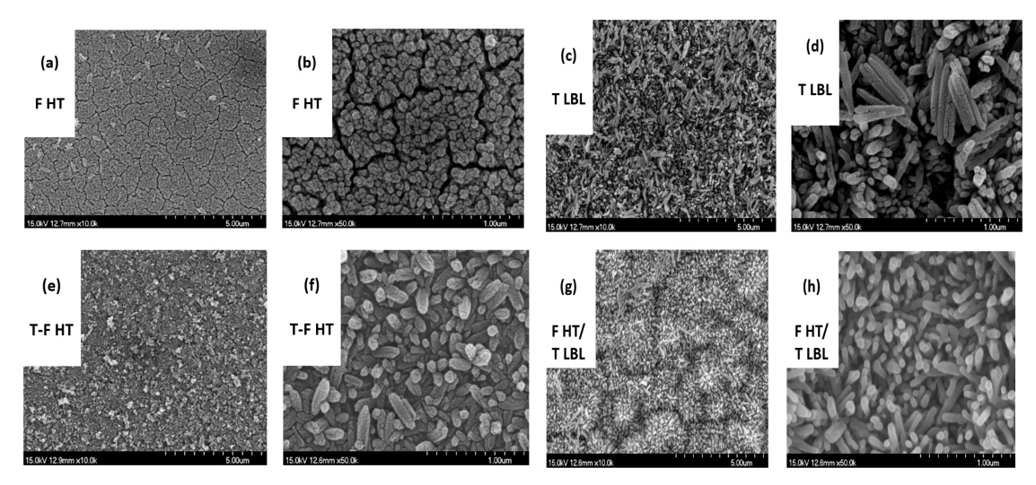
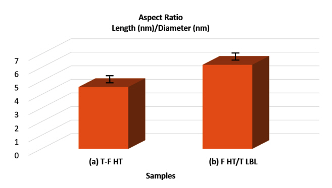
Manipulating particle size is a general strategy to improve the quality of a photocatalyst. Reducing the particle size of a photocatalyst enhances the density of the catalytic site surface and the photocatalytic activity due to the shortened diffusion length of photogenerated electron-hole pairs [33]. The surface morphology and particle sizes of F HT/FTO, T LBL/FTO, T-F HT/FTO, and F HT/ T LBL/FTO sintered at different temperatures (500, 550, and 750 ┬░C) are presented in the FESEM images in Figure 1 that illustrate different nanostructures. Figures 1 (a) and (b) present the uniform distribution of the nanorods of F-HT nanostructures on the FTO substrates. The growth of TiO2 by the LBL method on the FTO glass substrates exhibited short nanorod-like structures as indicated in Figures 1 (c) and (d). The T-F HT/ FTO sample presented in Figures 1 (e) and (f) exhibits short urchin-like structures. Figure 1 (g, h) presents sample F HT/ T LBL/ FTO that was synthesized by both LBL and HT methods in sequence and exhibits a short urchin-like structure. Therefore, samples exhibiting urchin-like nanostructures possess smaller feature sizes that may increase the aspect ratio of the effective interface of hematite and could be suitable for photoelectrochemical splitting. Furthermore, the smaller feature size causes the photogeneration of holes that are closer to the semiconductor liquid junction (SCLJ) [34]. Figure 2 indicates the aspect ratios of two samples with urchin-like structures.
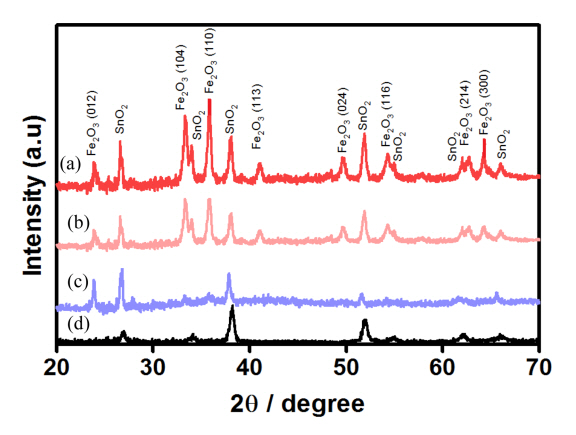
X-ray diffraction (XRD, Rint-2000, Rigaku) was performed with Cu K╬▒ radiation (╬╗=1.54056 ├ģ) at 40 kV and 100 mA at a scanning speed of 2 ┬░ min-1. Figure 3 presents the XRD data for samples (a) F HT/ T LBL, (b) T-F HT, and (c) F HT and for (d) bare FTO glass. T-F HT sample (b) exhibits enhanced crystallinity of hematite compared to that of sample (c) as observed from the increased intensity of the (110) and (104) peaks (the intensity of the [110] peak in T-F HT is stronger than is that of F HT). A general comparison of the intensity of the (110) XRD peak revealed that the sample F HT/ T LBL that was sintered at 550 ┬░C for 2 h. with an additional heat treatment for 10 min at 750 ┬░C yielded the best crystallinity. As described, the use of both the HT and LBL methods reduces the feature size, and this ultimately leads to improved crystallinity.
The measured photoelectrochemical performance of a 1 M aqueous solution of NaOH electrolyte is presented in Figure 4. The counter and reference electrodes were platinum (Pt) wire and saturated calomel electrode (SCE) Hg/Hg2Cl2, respectively, as illustrated in Figure 4 (1). Different substratebased photoelectrochemical cells that were sintered at 500, 550, and 750 ┬░C were used as working electrodes in the dark and under light illumination (100 mW cm-2 UV-Vis). The range of linear sweep voltammetry was between 0.0~+1.8 (V versus RHE). The photocurrent at 1.23 VRHE was increased for samples (c), (b), and (a) as illustrated in Figure 4 (3), and the highest value of 2.04 mA cm-2 was observed for sample (a). Sample (c) T LBL at 1.23 V vs RHE exhibited a low photocurrent density of 1.02 mA/cm2 as presented in Figure 4 (3). The photocurrent density of F-HT (sample [b]) at 1.23 V vs. RHE was observed at 1.84 mA/cm2.
The addition of TiCN as a precursor to the HT method resulted in the formation of new hematite nanostructures possessing an urchin-like morphology. In this structure, the electron-hole recombination is reduced and a high photocurrent density at 1.23 V vs. RHE is obtained. The achieved current densities for samples (a)-(c) are compared in Figure 4 (4). The photocurrent density of sample F HT/ T LBL at 1.23 V vs. RHE was remarkably increased as shown in Figure 4 (2) due to the use of a TiO2 underlayer. TiO2 acts as a barrier layer and prevents electrons from recombining in F HT/ T LBL photoanodes [35]. Thus, the TiO2 interlayer plays a significant role in the efficient collection and conversion of photon energy [36].
A schematic of the process for charge transfer and separation in sample F HT/ T LBL /FTO is presented in Figure 5. The photogenerated electrons of ╬▒-Fe2O3 under visible irradiation can be excited from the valence band (VB) to different energy levels of the conduction band (CB) (including the high-energy and low-energy regions). At a low energy level, the photogenerated electrons quickly relax to the VB bottom of ╬▒-Fe2O3 to recombine with the holes. However, high-energy electrons are thermodynamically transferred to the CB of TiO2, thus leading to the promoted separation of visible-excited charges [35-38].
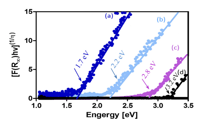
The optical band gap energy presented in Figure 6 reveals the effect of the LBL coating and doping layer arrangement on all four samples. Using both the HT and LBL methods and according to the highest obtained photocurrent density in Figure 4, the bandgap energy is decreased in sample F HT/ T LBL / FTO. Typically, electrons that gain energy that is equal to or greater than the bandgap energy in the valence state are excited to the conduction band. In this study, TiO2 nanocrystals were the center for recombining electrons and holes. By decreasing the bandgap energy and increasing the photocurrent density, the smaller urchin-like structure of the F HT/ T LBL / FTO sample acted as a photoanode and enhanced PEC water splitting.
4. CONCLUSION
This research study presents an enhanced water-splitting efficiency technique using a novel photoanode designed by utilizing LBL and HT methods. The morphology, particle size, and surface area all play important roles in the improvement of water-splitting performance, and thus, due to these factors and the effect of TiO2 as a compact layer between FTO and the ╬▒-Fe2O3 photoanode, the properties and water-splitting process are enhanced. A newly designed Fe2O3/TiO2/FTO (F HT/ T LBL /FTO) photoanode (sintered at 550 ┬░C for 2 h. with an additional heat treatment for 10 min at 750 ┬░C) demonstrated a current density of 7.68 mA/cm2. By applying both LBL and HT methods simultaneously, an innovative method is proposed that leads to the formation of urchin-like structures possessing smaller feature particle sizes. Eventually, decreasing the bandgap energy reduces the electron-hole recombination, and this leads to a much higher photoelectrochemical water-splitting efficiency.