


1. INTRODUCTION
In conventional manufacturing, parts manufacturing technology pathways can be classified into several categories, including melting-solidification, mechanical deformation, machining, and powder metallurgy. Additive manufacturing (AM) technology differs from these conventional manufacturing technologies [1-4]. In AM, parts are fabricated by the layer-wise stacking of 2 dimensional patterns sliced from 3 dimensional computer models. Unlike casting, deformation, and powder compacting, parts are produced without molds or tools. In essence, AM technology is based on bottom-up principles, in contrast to subtractive machining technology, and this improves its material utilization efficiency.
There are seven standard AM classifications, related to their consolidation mechanisms and processing principles [5]. In metal AM, metallic parts can either be directly fabricated (single-step process) or semi-final parts can be fabricated (multi-step process). Powder bed fusion AM, directed energy deposition AM, and sheet lamination AM methods belong to the single-step process category. Binder jetting AM and material extrusion AM are multi-step processes. The single-step processes have significant process-savings, however, they have limitations, including materials selectivity and uncertainties in product properties. On the other hand, multi-step processes fabricate semi-final products which need to be further densified.
Binder jetting AM is an AM process in which a liquid bonding agent is selectively deposited to join powder materials in ISO/ASTM 52900. The industrial adoption of metal binder jetting AM followed a process of continuous innovation, unlike single-step AM technologies. Binder jetting AM is currently used to fabricate green bodies which need to be further densified by conventional powder metallurgy processes. In practice, the binder jetting AM process can be used to replace metal injection molding (MIM) technology. In the AM process, metallic powder mixed with thermoplastic polymer feedstock is injected into molds and green bodies are ejected from the molds after solidification of the binder phases. The binder phases are removed by debinding processes and the brown bodies are further densified either by sintering processes or molten metal infiltration processes.
As previously noted, with binder jetting AM the green bodies can be fabricated without any molds. In addition, parts designs are less limited than those fabricated using MIM technology. However, layer-wise fabrication requires coarse and spherical powders, and this results in lower solid loading and reduced surface area in the green bodies. The AM green bodies also have larger shrinkage and lower sinterability, which are also challenging to overcome.
In green parts fabrication, the mechanical strength of the green bodies should be sufficient to retain their shape during subsequent processing, and to be fully densified during post-AM processes, should have higher powder packing density. The powder layers are typically laid by either a blade-like recoater or a roller-type recoater [6]. The density and microstructural homogeneity of the fabricated green bodies is determined by the powder bed density and packing uniformity, which are in turn affected by the powderŌĆÖs properties. The mechanical strength of the as-cured green body parts is determined by the consolidation of the powders in the polymerized binder phase. For liquid phase infiltration in porous dry media, the saturation behaviors of the aqueous binder are affected by structures in the powder bed and processing parameters. Accordingly, it is necessary to prepare homogeneous powder layers and to distribute the aqueous binder phase uniformly through selected regions in the dry powder layer.
In the present study, green parts were fabricated by binder jetting AM using commercial 420 martensitic stainless steel powders. The packing behaviors of the powders were observed by measuring powder bed density, in addition to standardized measurements such as apparent density and tap density. Green body properties were investigated according to their orientations while building parts.
2. EXPERIMENTAL PROCEDURES
2.1. Materials and processes
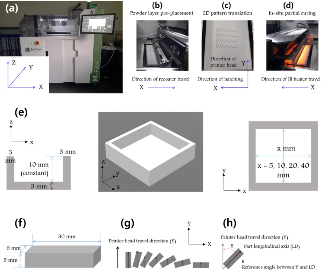
Commercial martensitic 420 stainless steel powder (S4230, ExOne, USA) and a standard aqueous-based binder (BA005, ExOne, USA) were used to fabricate the parts. Parts were built using an M-Flex (ExOne, USA) machine Fig 1 (a). Figure 1 shows a set of 2D patterns generated by binder jetting AM. Figure 1 (b) shows the powder pre-placed by a traveling roller-type recoater, which is rotating in the counterclockwise direction. Figure 1 (c) shows the 2D pattern generated by binder jetting from a travelling printer head, and Fig 1 (d) shows the partial curing of the binder jetted powder bed by travelling infra-red heater. The words Binder Jetting AM were printed by repeating the above process.
To evaluate the powder bed packing density, density measurement cup tests were conducted [7]. The density measurement cup models are described in Fig 1 (e). The model used for the bending strength measurement is shown in Fig 1 (f). The models were arrayed in a job box with changing reference angles from 0o to 90 o at increments of 15 o Fig 1 (g). The reference angle is defined as the angle between the printer head travel direction and the part longitudinal axis, as illustrated in Fig 1 (h). The process parameters for binder jetting AM are summarized in Table 1. The as-built parts were cured at 463 K for 8 hours in an inert environment. During the post-thermal curing, conversion to thermo-set polyester resin occurs, which allows the green bodies to retain their shapes [8] After thermal curing, the parts were removed from the job box and de-powdering was conducted.
2.2 Characterization
Particle size distribution, morphology, flowability, and packing behaviors were evaluated using standard test methods [9-15]. For the powder packing density calculation, and weight of powder in the inner volume was measured by an analytic balance, while the inner dimension of the 3D model was used to calculate volume. 3-point bending strength ascured green bodies was measured at 0.5 mm/min. After the bending tests, broken surfaces were examined by scanning electron microscopy and energy dispersion spectroscopy.
3. RESULTS
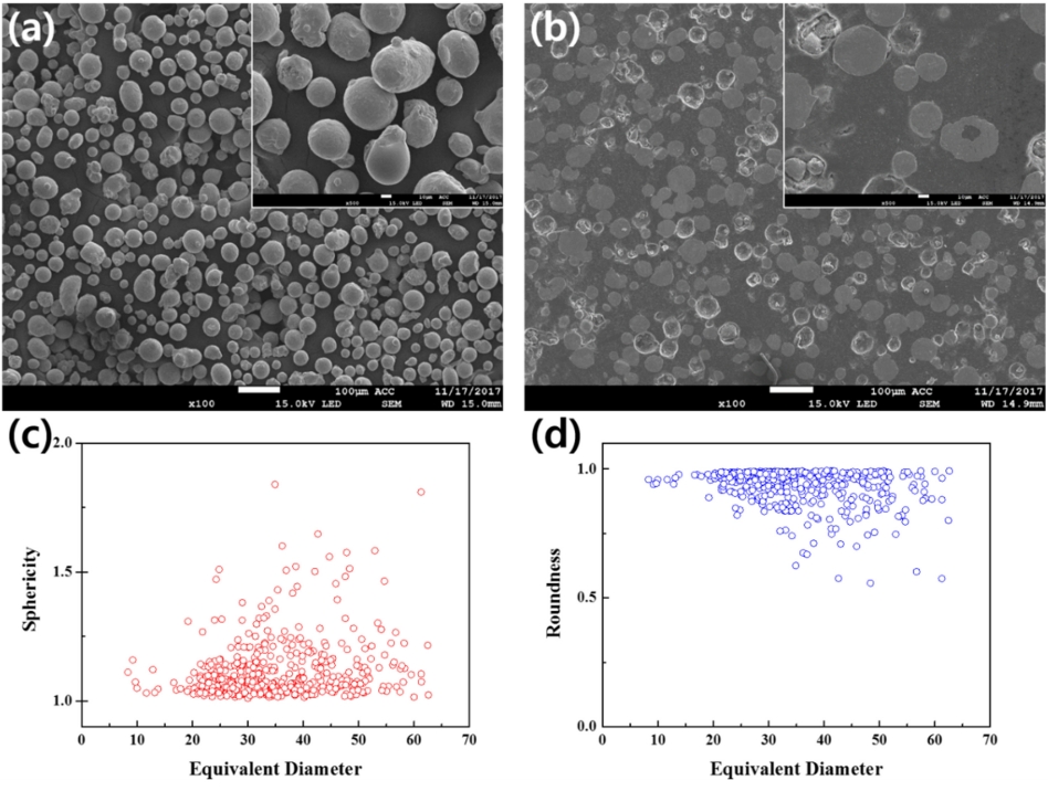
The plan-view, cross-sectional morphologies, sphericity and roundness of the feedstock powders are shown in Fig 2 and the size, flowabilities and packing densities are summarized in Table 2. The powders exhibit a typical morphology following the inert gas atomization process. Most of the powders are spherical but elongated powders are also present Fig 2 (a). They have smooth surfaces but satellite particles are attached to coarse powders. During gas atomization, a molten liquid is atomized to generate molten droplets. During flight, they are spheroidized, which reduces surface energy, and solidify into solid spheres. However, rapid solidification of fluctuating molten droplets will result in elongated powders. On the other hand, high-temperature collisions of in-flight particles causes sintered powders (i.e., satellite-attached powders). Internal pores are frequently observed as shown in the cross-sectional microstructures Fig 2 (b). Sphericity Fig 2 (c) and roundness Fig 2 (d) are calculated with reference to P. Singh and P. Ramakrishnan [16], and the closer the value is to 1, the closer the morphology and surface are to a circle. The morphology of the powder can be deduced through its sphericity and roundness, and the flowability of the powder can be indirectly confirmed.
The as-received powders showed monoidal size distribution. From the particle size distribution, d10, d50, and d90 were 25.7, 40.7, and 64.2 um, respectively. The apparent density was 4.18 g/cm3 and tap density increased to 5.26 g/cm3. The Hausner ratio (tap density/apparent density ratio) was 1.26, which from GeldartŌĆÖs classification belongs to semi-cohesive powders [17]. In general, the flowability of powders is poor when the Hausner ratio is higher than 1.4 [18,19]. However, in this study the powders had good flowability as indicated by the values in Table 2.
Density measurement cup tests were conducted to directly measure the packing density of the powder bed according to the literature [7]. However, density-measurement cups with different dimensions were prepared in order to verify size dependency in the measurement. As shown in Fig 1 (e), the inner vacant volumes of the density-measurement cups were 5 ├Ś 5 ├Ś 10 mm3, 10 ├Ś 10 ├Ś 10 mm3, 20 ├Ś 20 ├Ś 10 mm3, and 40 ├Ś 40 ├Ś 10 mm3. The density-measurement cups were placed in 1, 2, 3, and 4 quadrants, respectively, per size. After the process, the packing densities of the powders which were placed in the inner volumes were determined to be 4.72, 4.67, 4.66, and 4.65 g/cm3, respectively (Fig 3).
Within the scope of this study, powder bed density was found to be the same regardless of the dimension of the density measurement cup. Using these results, the spatial uniformity of the powder bed density was evaluated by placing a density measurement cup model with an inner vacant volume of 10 ├Ś 10 ├Ś 10 mm3 through the job box. The measured packing densities showed similar values, so the powder bed density in the job box was considered to be uniform. The density measurement cup tests showed that the powder bed density was between the apparent density value and the tap density value due to powder rearrangement by the recoater roller.
4. DISCUSSION
4.1 Powder characteristics and packing behaviors
In AM processes, powder characteristics have a critical influence on the processing ability and the properties of parts. Powder-based AM technologies require powder beds with higher packing density, smaller pore size, and uniform pore size distribution are required. Accordingly, free-flowing powders with a spherical morphology and monoidal size distribution are standard feedstock powders.
For binder jetting AM in particular, the design of the feedstock powder should take both AM process and post densification into consideration. In the present study, the powder bed was incrementally developed by layering a certain thickness of powder layer onto the surface of a previously processed layer. In this way the powders had sufficient flowability to reach a random packing arrangement but were still stiff enough to maintain that packing structure against external forces during powder layering.
Satellite powders on the micro-spheres increase their surface roughness, which deteriorates flow by enhancing interparticle friction. In contrast, powder bed stiffness is improved by stabilizing the powder configuration in packed powders. Green body properties are partially determined by the powder bed packing density, and in turn, postdensification processes are affected by the green body properties. In the literature [20], binder jetted parts composed of gas atomized 625 powder have higher green density than water atomized parts. The shrinkage rate is faster for wateratomized powder, but the final density is higher for the gas-atomized powder.
For spherical powders, particle size distribution influences sinterability as well as packing behavior [21], and bimodal feedstock powder size has been explored for binder jetting AM. In spite of all efforts to elucidate relationships between powder properties, AM processing ability, and post-densification behaviors, it is still difficult to predict powder behaviors over the entire lifecycle of binder jetting AM-based full-density parts manufacturing. In fact, while the STS 420 feedstock powder had a relatively high Hausner ratio, the powder bed had a random packing density of 60.76% with uniformity through the job box. Powder bed rheology tests have been proposed to address the limitations of current standardized test methods [22,23]. Nevertheless, the density measurement cup test emphasizes direct evaluation to determine the packing density of the powder bed. In addition, density measurement cup tests can be employed to assess the reliability of powder bed packing through the job box, as well as the reproducibility of powder bed packing during repeated AM processing. It can also be utilized as a witness sample for powder packing in the green body.
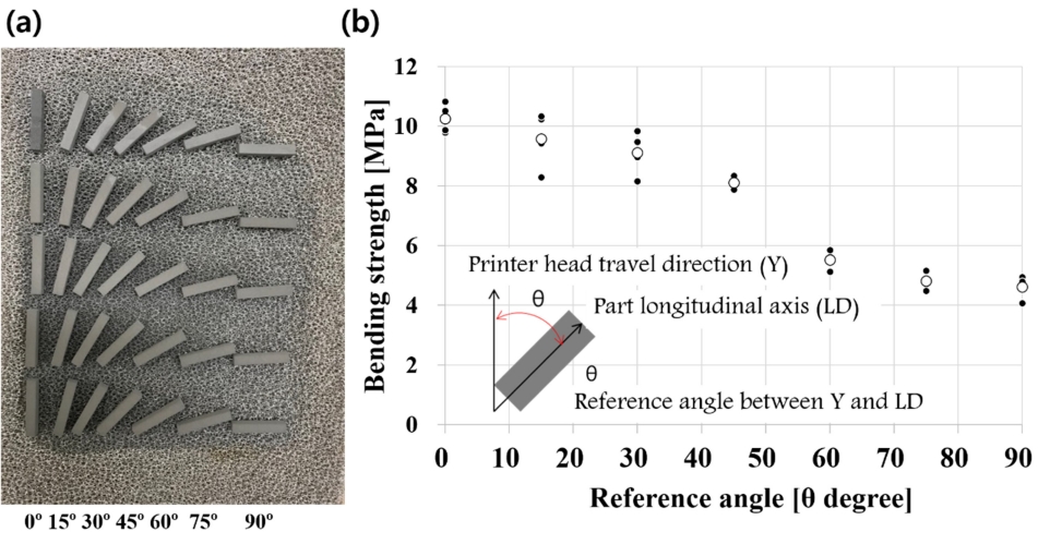
The shapes fabricated according to additive direction are presented in Fig 4 (a) and the bending strengths of the ascured samples are shown in Fig 4 (b). The green bodies have sufficient mechanical strength for handling, but they show orientation dependence. As the reference angle between the printer-head travel direction and the part longitudinal axis increases, bending strength decreases. When the longitudinal axis of the part is parallel to the printer-head travel direction (the sample with a reference angle of 0┬░), the green body sample had the highest bending strength, of 10.25 MPa. On the other hand, the green body sample with a reference angle of 90┬░ had the lowest strength, of 4.61 MPa.
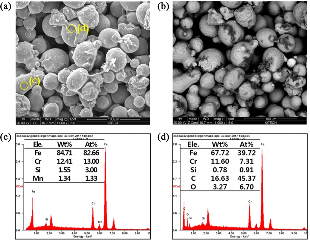
Representative microstructures of the as-cured parts are shown in Fig 5. The powders are randomly packed with the dispersion of the polymerized adhesive binders. The region marked in Fig 5 (c) is an intact surface of powder and Fig 5 (d) is a powder surface covered with binder, as expected from the energy dispersion spectra. The binder phase forms a pendular bond at the contact interfaces between particles as can be seen from the back-scattered electron photograph Fig 5 (b) in which lighter binder phases have dark contrast. In summary, most of the powder surfaces are intact but the adhesive binder phases form local aggregates with the powders, which helps the green body retain the overall part shape.
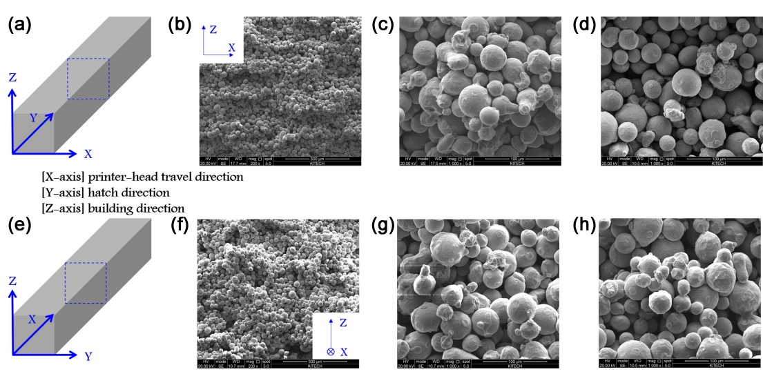
Figure 6 shows the representative fractured-surface microstructures of the fabricated green bodies. The X, Y, and Z directions correspond to the printer-head travel direction, hatch direction, and building direction, respectively. The fractured surface in Fig 6 (a) came from the X-Z plane. Here, the printer-head travel direction is parallel to the fracture. On the other hand, in the case of Fig 6 (e), the fracture occurred through Y-Z plane, vertical to the printer-head travel direction. Figure 6 (a) shows periodic perturbations along the Z-building direction. Figure 6 (b) shows a horizontal line on the fracture surface and Fig 6 (f) shows an irregular fracture surface. In this part, it can be clearly observed that tin he Y-axis direction the print head ejects the binder, causing the anisotropy in bending strength.
Powder-polymer bonds form powder agglomerations, which are marked in Fig 6 (c). However, the polymer binders are difficult to observe in the marked Fig 6 (d) region, where the powders are loosely packed. In contrast, the Fig 6 (e) surface shows quite different microstructures from Fig 6 (a). Random and rough domains with dimple-like cavities can be seen. There is a difference in the polymer bond phase distribution. The polymer phases are well dispersed at inter-particles in both regions shown of Fig 6 (g) and Fig 6 (h). This reveals that the anisotropy in bending strength is related to the polymerized binder distribution, according to their orientation in the parts.
4.2 Anisotropy in the as-cured part strength
During the 2D pattern translation on the pre-placed powder layer, binders are jetted through multiple-arrayed nozzles on the traveling print head. Each traveling nozzle leaves a line-like footprint on the powder bed. When the spreading rate of a single binder droplet impinging on the surface of the powder layer is fast, the binder is flattened and achieves an equilibrium three-phase boundary. After that, volumetric shrinkage occurs by migration of binder from the flattened droplet to pores.
If a liquid droplet is impacted vertical onto a stationary surface, internal pressure is built in the binder at the moment of impingement on the rigid surface. This causes mass flow and flattening as well as radial expansion occurs. Kinetic energy is dissipated by the viscous forces of the spreading liquid and the generation of surface energy. A symmetrically flattened droplet is finally developed in this case.
In contrast, aqueous-based binder droplets are ejected toward stationary substrate surfaces from a moving nozzle, which is typical of ink-jet printing technology, including binder jetting AM. As a result, asymmetric spreading of the impinging droplet can be expected because tangential velocity as well as normal velocity is developed in the droplet [24]. Asymmetrically flattened liquid droplets are able to penetrate into the open pores of the powder layer. The penetration behaviors and morphological evolutions of liquid droplets into dry porous media are important, since binder saturation and binder distribution affect the final configuration and continuity of the powder-polymerized resin bonds in the green body. In addition, the solvent in the binder is evaporated and this affects the viscosity of the penetrating binder. Therefore, the penetration kinetics are also important.
Theoretical models for droplet infiltration into porous media are described in relation to changes in the diameter of the drawing area [25]. The two limiting cases are designated a decreasing drawing area (DDA), and a constant drawing area (CDA). During penetration, the drawing area is decreased if the contact angle of the flattened droplet remains constant. This is the case for DDA. On the other hand, for CDA the drawing area is constant, so the contact angle is decreased until the flattened binder volume is depleted. Although the morphologies of the binder-powder mixture and infiltration kinetics are different, binder penetration is driven by capillary force in both cases.
In binder jetting AM, binder saturation is practically defined as the binder volume/pore volume ratio [26,27]. During the binder jetting process, the aqueous-based binder is a wetting phase, while air is a non-wetting phase in the porous powder bed. The aqueous binder penetrates pores by displacing air (imbibition), which increases the binder saturation in pores. In contrast, drainage from the binder-saturated region into the surrounding powders reduces the overall binder saturation ratio. Equilibrium binder saturation is achieved by achieving a balance between imbibition and drainage [25], and the morphology of the stabilized binder-powder mixture is changed: stable displacement and finger-like displacement [25].
Until now, the impingement and infiltration behaviors of a single aqueous droplet have been considered. During the 2D pattern translation, binder droplets are periodically ejected and each binder forms a binder-powder mixture. The binder-powder mixture resulting from a single droplet is regarded as a building block for the line-like footprint. The 2-D pattern is an in-plane collection of hatch lines produced by binder jetting from multiple nozzles, which are installed on the printer head. Therefore, overlapping degrees of binder-powder mixtures should be considered along the printer-head travel direction, hatch direction, and part building direction.
The in-line continuity of the binder-powder mixtures depends on the dimensions of the mixture and the distance between neighboring impinging binder droplets, which in turn depends on droplet size and printer head travel speed. At the same time, the in-plane continuity of the footprint hatch lines is affected by the vertical permeation length of the binder and nozzle distance. Z-axis continuity is determined by the vertical permeation length and powder layer thickness. The infiltrated binder is partially polymerized following solvent evaporation during in-situ IR curing. Evaporation of the solvent and polymerization is further enhanced by post thermal curing. Accordingly, the dimensions and pattern morphologies of the aqueous binder-powder mixture and overlapping degrees affect the macroscopic connectivity of the polymerized bonds in the green body.
From the results for bending strength and the fractured surface microstructures, Z-axis continuity as well as in-line continuity seems to be good. However, overlapping between hatching lines introduces discontinuity. As a result, fracture propagation is more prevalent along the weakly overlapped hatch direction. This causes the orientation-dependent bending strength observed in the green bodies. This will be further proven by changing the binder saturation degree and printer-head travel speed in the future.
5. CONCLUSION
420 martensitic stainless steel green bodies were fabricated by binder jetting AM and post-thermal curing processes. The powder packing density of the powder bed was measured by density measurement cup test. The powder bed density was 60.76%, which lies between the apparent density value and the tap density value, and was uniform through the entire powder bed. After thermal curing, the polymerized binder phases bonded the powders, and the resulting pendular structure-like powder-binder bonds retained the shape of the green bodies. The bend strength for the vertical to printerhead travel direction was two times higher than for the travel direction parallel to the printer-head. The orientation-dependent bending strength seemed to be due to the asymmetrical spreading and insufficient penetration of the aqueous-based binder vertical to the printer-head travel direction, and the resultant discontinuities in binder phase distribution between hatch lines. In conclusion, it was confirmed that when using binder jetting AM, the direction of binder jetting affects the bending strength of the green body when the powder bed density is uniform.