


1. INTRODUCTION
Steel is one of the most important materials for engineering and manufacturing. Generally, the following four processes are required to fabricate a steel product: smelting, steel making, continuous casting, and hot rolling. Continuous casting and hot rolling processes are the most widely used. Both have the advantages of shape complexity, mass production, and cost effectiveness [1,2].
However, there are some discontinuities between the conventional continuous casting and the hot rolling processes. The discontinuities may decrease product quality such as, surface roughness, and homogeneity. When using a hot rolling mill, producing thin steel plates is very difficult and results in low surface quality and low strength, because of surface oxidation due to the temperature drop.
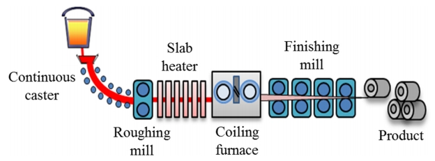
Therefore, a new process, called the Compact Endless cast and rolling Mill (CEM) was developed by Pohang Iron & Steel Company (POSCO) [3]. CEM is an advanced process technology that combines continuous casting and the hot rolling process, and it has many advantages. CEM processes can make mass production with high quality slabs. Additionally, thin products which are very difficult to produce by hot-rolling can now be easily manufactured. With the proposed method, it is possible to maintain the uniform high quality of hot-rolled products, which were once difficult to fabricate using conventional hot-rolling or casting. Figure 1 shows the layout of the CEM process.
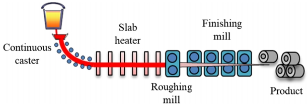
First, the hot slab is moved from the continuous caster and passed through the slab heater to reheat for temperature recovery and homogenization. Next, the slab is moved into the coiling furnace and finishing mill to conduct coiling and adjust sizing. However, the coiling furnace is a very expensive device and has high maintenance costs. Therefore, the new proposed layout as shown in Fig 2 can overcome this drawback.
In the new layout, the slab passes through the slab heaters and is shaped in the finishing mill. The gap between the slab heaters was increased and not covered, so the slab temperature rapidly dropped when the slab was passed through the slab heater. In the steel-fabrication process, the temperature distribution is the most important parameter determining slab quality [4-11]. Temperature distribution also affects the kinetic and kinematic parameters, such as stress, strain, and deformation, which are directly related to quality [12,13]. Moreover, these effects impact the hardness or ductility of a slab [14,15]. Variation of temperature can be decreased by using a slab heater cover between slab heaters.
In this study, thermal and structural analysis in the slab with slab heater covers were conducted for new the layout CEM process. Simulation results were verified by comparing them the experimental results. A sensitivity analysis of the slab heater cover was carried out to determine the greatest influence on the slab temperature and deformation.
2. THEORY
In the CEM process, heat transfer from the heater to the slab depends mainly on radiation, because of the high temperature difference. Heat conduction is the dominant heat transfer inside the slab and the slab heater. The heat transfer by the radiation can be determined using equation (1): [16]
where N is the number of radiating surfaces, δji is the Kronecker delta, εi is the effective emissivity of the surface i, Ai is the area of surface i, Qi is the energy loss of surface i, σ is the Stefan-Boltzmann constant, and Ti is the absolute temperature of surface i. Fji contains the radiation view factors, which are defined as the blocked fraction of total radiant energy by the surface i, as shown in Fig 3 and expressed by equation (2):
where Ai and Aj are the areas of surfaces i and j respectively, r is the distance between differential surfaces i and j, θi and θj are the angles between normal vectors, Ni and Nj, and the radius line to surface d(Ai) and d(Aj), respectively.
Heat transfer by conduction can be described as equation (3) [17]:
where ρ is the material density, c is the specific heat, k is the thermal conductivity, and Ew is the energy input due to mechanical work. Ew is zero because CEM process receives no external energy input.
Using the temperature distribution obtained from equations (1) to (3), the thermal stress can be calculated by equation (4): [18]
where E is Young’s modulus, α is the thermal expansion coefficient, T is the current temperature, and T0 is the initial temperature.
3. GEOMETRY AND MATERIAL PROPERTIES
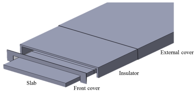
Figure 4 shows the slab heater cover design for the CEM process. The slab heater cover consists of three parts: the front cover, the insulator and the external cover. The slab passes through the slab heater cover. SS400 was used for the front and external covers, and Ceramol#150 was used as an insulator. The slab was provided by POSCO. The mechanical and thermal properties of the slab, cover and insulator are summarized in Table 1.
4. RESULTS AND DISCUSSION
4.1. Simulation verification
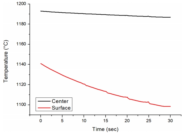
A cooling experiment was conducted to verify the simulation. A schematic diagram of the experiment is shown in Fig 5. The cooling time was 30 seconds, and the temperatures at the surface, and the center of the slab were measured by thermocouples. The average temperature was obtained by calculating the temperature of each thermocouple. The results of the cooling experiment are shown in Table 2.
Comparing the experimental and simulation results (Table 2, 3 and Fig 6), the surface temperature differences between the start and the end were respectively 53 °C and 55.3 °C. The average temperature differences were 16 °C and 12.8 °C, and the center temperature differences were 11 °C and 9.4 °C, respectively. The errors between the experimental and simulation results were all within 3 °C. Thus, the simulation was verified.
4.2. Slab heater cover effect
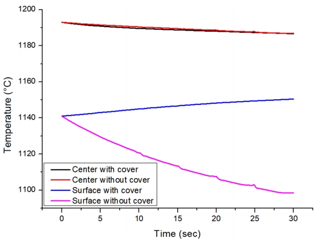
To study the effect of the slab heater cover, the simulation results of the temperature with and without slab heater during cooling were compared as shown in Fig 7. The differences in center temperatures with and without cover cases were very small, within 3 °C, but the surface temperature differences were larger. The center temperature was cooled by conduction, but the surface temperature was chilled by convection and radiation. The amount of cooling by conduction is governed by the temperature difference between the center and the surface, while heat transfer by convection and radiation are determined the temperature difference between the atmosphere with room temperature and the surface. Therefore, there was no significant difference in the center temperature after cooling regardless of the presence of the cover. In the absence of a cover, the temperature differences between the surface and atmosphere remained almost constant because the atmosphere was maintained at a constant temperature (room temperature). However, in the opposite case, the bottom surface of the cover was heated by the slab surface, so heat fluxes were decreased. Therefore, the slab heater cover is effect on the reduce of temperature gradient of the slab.
4.3. Simulation results
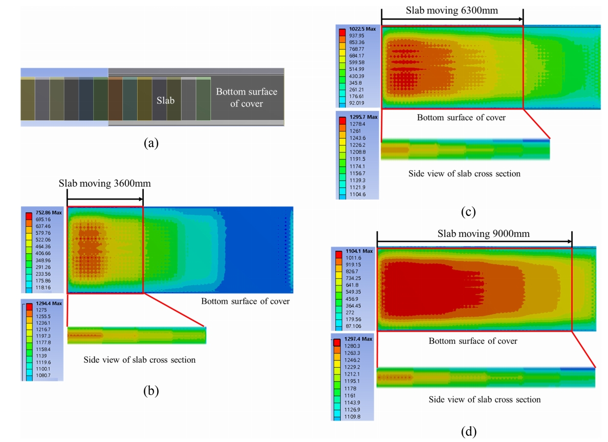
Because of the characteristics of the CEM process, a slab can be produced in an infinite length. However, it is impossible to deal with the infinite length of the slab in a simulation. Therefore, it would be useful to determine the moving distance of a slab with an unchanging average temperature. Figure 8 and 9 show the simulation conditions and results of temperature distribution, respectively. Figure 10 shows the average temperature of the slab with respect to the slab moving distance.
The initial temperature of the cover and atmosphere were set to room temperature. The dominant heat transfer method was radiation from the heater to the slab due to the slab’s high temperature compared to its surroundings. Heat transfer caused by natural convection also occurred. The coefficient of natural convection was set to 5 W/m2K. The slab moved at 6 m/min, which was the optimal speed for the new layout as determined by POSCO [3].
Initially, a slab with the temperature distribution defined in Fig 8 was inserted into the cover at room temperature and the bottom of the cover was gradually heated. At this time, a slab that was not inserted into the cover was kept at the initial temperature distribution, and conduction occurred inside the slab. When the temperature of the bottom of the cover was increased above a certain level, the conduction effect inside the slab became larger than the heat transfers between slab and cover. Thus, the average slab temperature was moderately increased. The increased rates decreased and became zero when the slab moving distance reached 9000 mm. In other words, steady-state simulations can be performed after the saturation point.
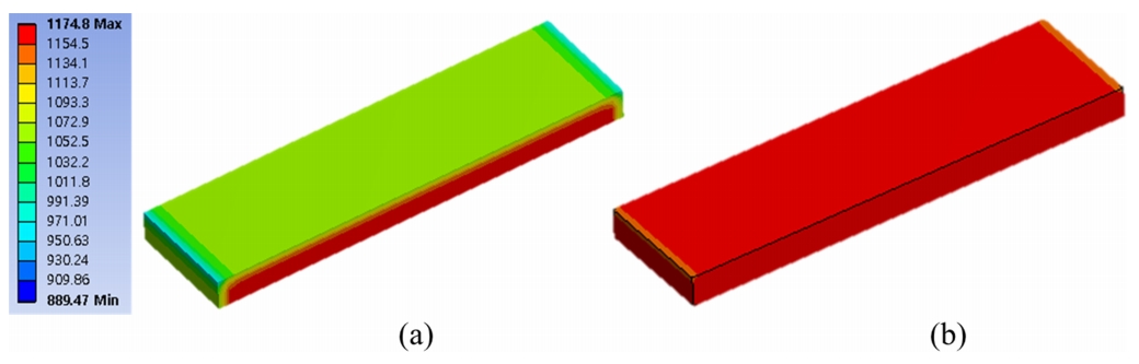
Based on the above results, thermal analysis of slab temperature distribution was conducted to investigate the efficiency of the cover during the CEM process shown in Fig 11.
The rate of temperature drop decreased by more than 50% when the slab heater cover was used. Furthermore, the temperature distribution was more uniformed, which contributed to improving the quality of the slab.
4.4. Sensitivity analysis of the slab heater cover
Sensitivity analysis is a quantification method to indicate the influence between the input and output parameters. Through sensitivity analysis, output parameters such as slab temperature, thermal stress, thermal strain, and total deformation were compared to design the slab heater cover. The sensitivity parameters were normalized to derive the correlation of variables regardless of the magnitude of values. Sensitivity is defined in equation 5 [19].
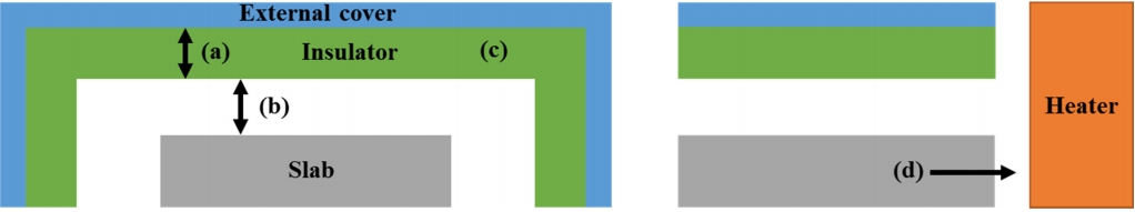
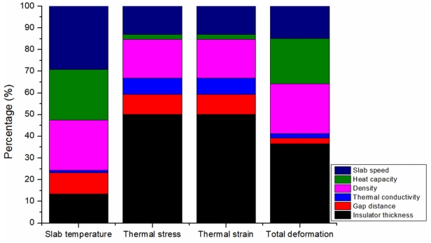
For the sensitivity analysis, the input parameters were varied ±30% and the subsequent changes in the output parameters were examined. Figure 12 shows the input parameters for the sensitivity analysis. The sensitivity results are summarized in Fig 13 and Table 4.
With respect to slab temperature, the slab speed was the most dominant factor. When the slab moved faster, the heat transfer rate between the slab and other materials, such as the insulator, decreased. The material properties of the insulator were also an important factor.
Heat transfer can be calculated using equation 6, where Q is the heat transfer, c is the specific heat, r is the density, V is the volume of the substance, and ΔT is the temperature gradient. The heat transfer is proportional to the density and specific heat.
Specific heat is one of the most sensitive material parameters. Material properties affect the radiation and conduction, so they affect the temperature changes of the insulator in response to the effect of the slab heater.
In the aspect of kinetics, thermal stress was most affected by insulator thickness. A high thermal stress could cause cracks and distortions in the insulator and body of the slab heater cover [20]. Density and slab speed also affect the kinetic parameters because the temperature difference between the slab and insulator cover increases as either parameter increases.
The slab heater is composed of an insulator, a cover, and a slab, which are linear elastic materials. Therefore, the stress and strain followed the Hooke’s law. Thus, the results of the sensitivity analysis for the thermal stress and the strain are the same. Finally, deformation in the vertical direction was most affected by the insulator thickness because the temperature gradient increased as the insulator thickness increased. In addition, a large temperature gradient caused an increase in thermal stress and strain, so the deformation in the vertical direction increased. The material properties of the cover (density and heat capacity) were also important parameters.
5. CONCLUSION
Use of a slab heater cover was effective in reducing the temperature drop in the slab during CEM. This paper presented a sensitivity analysis of the slab heater cover using FEM methods to identify the parameters that are important in designing the cover. Prior to the sensitivity analysis, simulation verification was performed by comparing experimental and simulation results. The results verified the efficiency of the slab heater cover in reducing the temperature drop during the CEM process was verified. Temperature was most affected by material properties such as density, heat capacity and slab speed. Kinetics and kinematics were most affected by the insulator thickness; density was also important. These simulation results for the slab heater cover provide information about the factors that are important in the design of a slab heater to increase efficiency. This work contributes to understanding of the CEM process, but can also be applied to other high-temperature steel-production processes such as rolling and casting.