


1. INTRODUCTION
Nodular graphite cast iron is widely used in the railway and automotive industries because it offers enhanced mechanical properties, such as crack resistance, improved ductility, workability, wear resistance, as well as excellent strength and hardenability [1-4]. In steel, austenite undergoes a metastable transformation into ferrite and cementite; however, in cast iron, the eutectic transformation consists of both a stable reaction, which involves the formation of ferrite and graphite, and a metastable reaction, which involves the formation of pearlite [5,6]. As a result, the matrix formed around the spherical graphite in nodular graphite cast iron is determined by a solidification process and a solid-state transformation. The mechanical properties of nodular graphite cast iron are affected by changes in formation, and the resulting fraction of each structure [7]. Typically, the matrix surrounding the nodular graphite forms a phase known as the bull’s eye, which increases the abrasion resistance and compressive strength of the nodular graphite cast iron [8].
GCD600 alloy is a nodular graphite cast iron material that contains a precipitate of the bull’s eye phase. This alloy is mainly used for the production of materials requiring high surface hardness, such as the wheels of excavators and railway tracks, because of its high strength and surface hardness [9]. In addition, like other nodular cast irons, the mechanical properties of this alloy are related to the number, size, and shape of the nodular graphite, and the fraction of pearlite and ferrite that form the matrix around the nodular graphite [7,10].
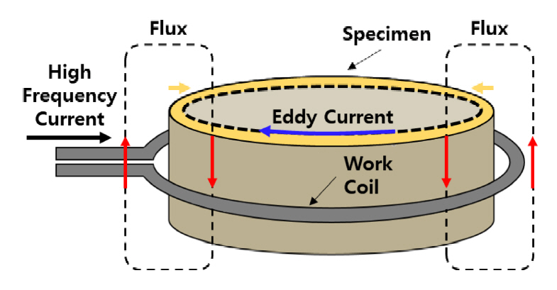
Several studies have investigated the use of a chemical modification method (to change the content with additional elements in the alloys) and heat treatment to modify the microstructure of the nodular cast iron, to improve its surface hardness [10-12]. Sn, as a pearlite stabilizer, is known to improve the strength and hardness of nodular graphite cast iron by increasing the density of the pearlite structure [13,14]. Therefore, this study employed Sn for the chemical modification treatment of GCD600. In addition, a high-frequency heat treatment (HF–HT, Fig 1), one of the surface hardening methods for reducing the decarburization phenomenon in nodular cast iron or deformation of the material, was employed to improve the surface hardness of the nodular cast iron. This method preserves the internal toughness of the nodular cast iron and can be employed in cases where impact must be considered [15]. The reason for improving the surface hardness is because there is a relationship between surface hardness and friction–wear properties [16,17,18]. For these reasons, it is essential to investigate the effects of each surface hardening method on the wear resistance characteristics of nodular cast iron, to understand how the friction–wear properties can be effectively improved.
In this study, surface hardening of GCD600 alloy was performed through chemical modification treatment via the addition of Sn, and the HF–HT method, and a comparative analysis of the correlation between the microstructure and friction–wear properties of each case was performed.
2. EXPERIMENTAL PROCEDURE
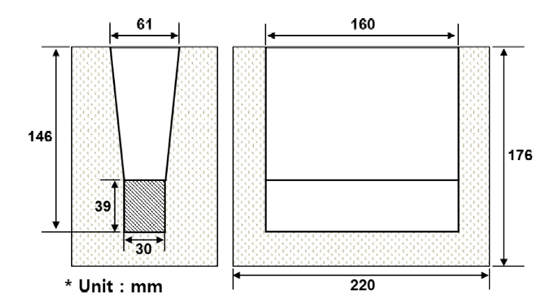
Figure 2 shows the shape and dimensions of the Y-block mold used in this study. The chemical composition of the GCD600 alloy manufactured using gravity casting is presented in Table 1. Since the addition of excessive Sn increases brittleness [14], an appropriate amount of 0.064 wt.% Sn was added to the material. The specimens were labeled as GCD600 (as-cast state testing material), GCD600Sn (Sn-added testing materials), GCD600H (HF–HT testing materials) and GCD600HSn (Sn-added and HF-HT testing materials). HF–HT was performed in three steps after the casting process, and the detailed conditions are shown in Table 2.
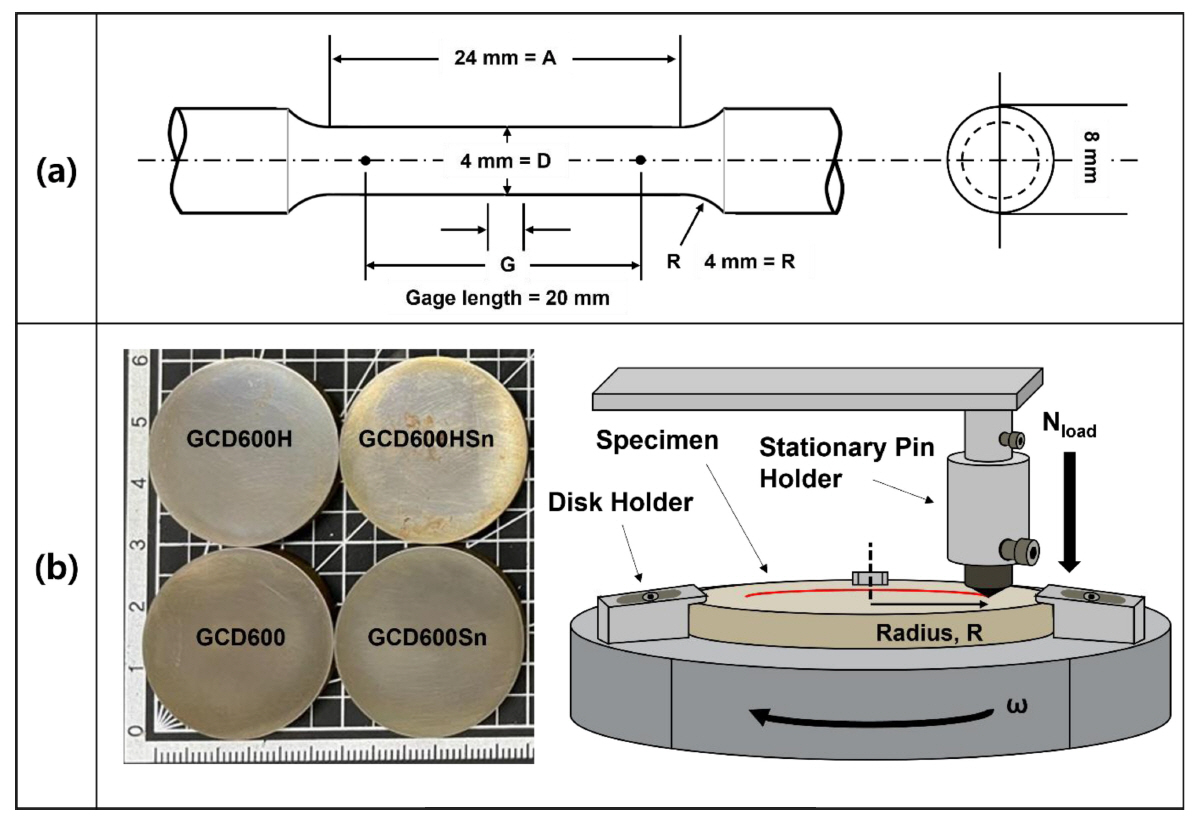
To investigate the mechanical properties of the specimens, hardness and tensile tests were performed. Hardness was measured using a Vickers hardness tester (Matsuzawa MMT-X7) at a load and fixation time of 0.01 kgf, and 10 s, respectively. Specimens for the tensile tests were manufactured as the No.14 specimen according to the KS B0802 (2008) test standards (Fig 3a). Then the tensile strength, yield strength, and elongation of each specimen were measured using a tensile tester (INSTRON 8501). Briefly, each specimen was polished, after which the surface was etched using a nital etchant (95% ethanol, 5% nitric acid) to reveal the bull’s eye phase and matrix, and the microstructure was analyzed using an optical microscope (ZEISS Axio). Subsequently, the nodularity of the nodular graphite and the fraction of each phase in the material were calculated using analysis software (IMT i-Solution DT). The nodularity indicates how spherical the shape of nodular graphite is, and was calculated according to the KSD 4302 standard.
To analyze the effect of microstructural changes on the friction–wear properties, friction–wear measurements were performed using the pin-on-disk method (Fig 3b). For this analysis, a diamond-made pin with a diameter of 1 mm was used as the counter material, and each specimen was prepared as a disk with a diameter of 3 cm (Fig 3b). The friction–wear test was conducted for a total of 5,000 seconds under the same load and fixed linear speed conditions of 20 N and 0.5024 mm/min, respectively. After the test, the correlation between the microstructural change and the friction–wear properties was confirmed by analyzing the worn surface using scanning electron microscopy (SEM, JEOL JSM 6390A) and a shape measuring laser microscope (Keyence VK-X250).
3. RESULTS AND DISCUSSION
The tensile test and hardness measurement results of each specimen are listed in Table 3. The results revealed that the chemical modification using Sn resulted in a slight increase in both the tensile strength and yield strength, but a significant reduction in elongation, from approximately 8 to 4%. In addition, the surface hardness of the GCD600Sn specimen increased slightly to approximately 30–50 HV. In contrast, the yield strength and tensile strength of the GCD600H specimens increased by approximately 30 MPa, but there was no significant difference in elongation. In addition, the hardness increased by more than approximately 150 HV, which corresponded to an increase from 90 to 100 HRB to 38 and to 42 HRC when substituting the Rockwell scale.
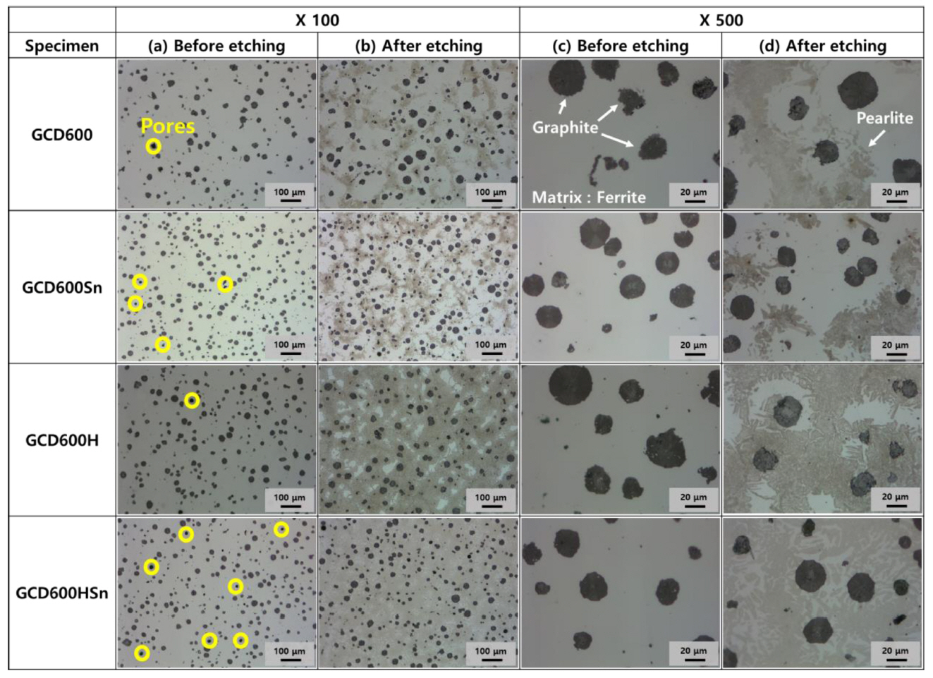
Figure 4 shows the optical microscopy images of the microstructure of the GCD600, GCD600Sn, GCD600H, and GCD600HSn specimens. The nodularity of each specimen and the fractions of graphite, ferrite, and pearlite in each image were measured, and are listed in Table 4. Sn is known to play a role in stabilizing pearlite in nodular cast iron, and it acts as a barrier to prevent the movement of carbon elements by remaining on the front edge of the unsolidified molten iron. Consequently, this suppresses diffusion and the growth of the nodular graphite [5,19,20]. Decreasing the size of the nodular graphite, a component of nodular graphite cast iron, results in an enhancement of the mechanical properties. Increasing the Sn content suppresses the growth of the nodular graphite, thus improving the strength and hardness of the nodular graphite cast iron. The size of the nodular graphite in the specimens with higher Sn content (GCD600Sn, GCD600HSn) was relatively small (20 µm or less), and the nodularity was relatively high. Specifically, the results revealed that the nodularity of GCD600Sn and GCD600HSn increased by approximately 9 and 4%, respectively (Table 4). However, a further increase in the Sn content resulted in a reduction in the diffusion time of graphite atoms, thus increasing the supercooling tendency of the specimen and promoting the formation of brittle cementite [21,22].
A ×100 magnified image of each specimen before etching (Fig 4a) revealed that the number of pores (yellow circles) formed in the matrix increased with increasing Sn content. This resulted in a decrease in elongation. In addition, after etching (Fig 4b), the fraction of ferrite in the Sn-containing specimens decreased and the fraction of pearlite increased, due to the stabilizing effect of Sn on pearlite. In addition, the fraction of pearlite increased, which enhanced the mechanical properties of the specimens [20]. Furthermore, in the GCD600H and GCD600HSn specimens, there was a significant transformation of the portion of the ferrite matrix into pearlite, and the area occupied by pearlite in the specimens increased significantly, to more than 75%. Compared to the as-cast specimen, the GCD600H and GCD600HSn specimens exhibited significantly increased strength and hardness, which is consistent with the findings of previous studies. They reported an improvement in the hardness and strength of nodular graphite cast iron containing an increased fraction of pearlite, compared to nodular graphite cast iron with a ferrite matrix, due to an increase in the fraction of pearlite [7,10].
The ×500 magnification images revealed that the graphite nodules were smaller and rounder after the addition of Sn, and the ×100 magnification images revealed that HF–HT resulted in the transformation of the matrix into pearlite (Fig 4c and 4d). In summary, the addition of Sn resulted in an increase in the strength and hardness of the specimen due to changes in the matrix and the nodular graphite; however, the addition of Sn resulted in a decrease in elongation, due to an increase in the number of pores. In contrast, HF–HT resulted in an increase in both the strength and hardness of the specimen, resulting from the major transformation of the matrix of the specimen into pearlite, and there was no significant change in elongation.
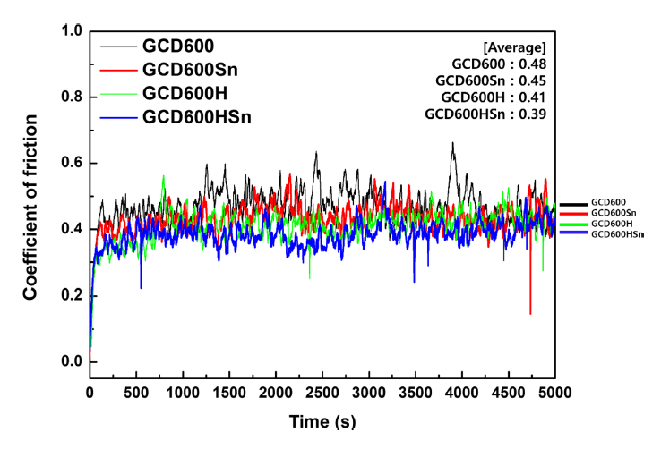
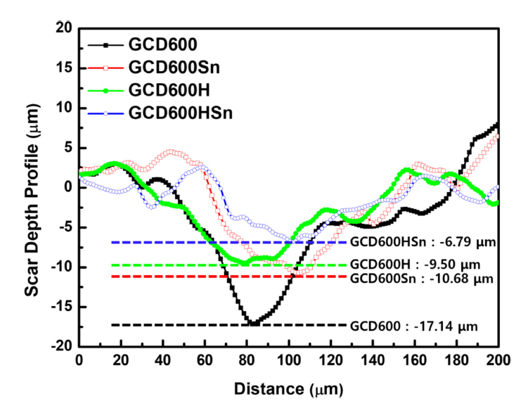
The average friction coefficient values of each specimen obtained using the pin-on-disk test are shown in Fig 5. The results revealed that the GCD600 specimen with the lowest hardness value exhibited the highest friction coefficient value, 0.48. In addition, as the surface hardness increased, the coefficient of the samples gradually decreased, to 0.45 for GCD600Sn, 0.41 for GCD600H, and 0.39 for GCD600HSn. This could be attributed to the increase in adhesion between the pin and the disk with the increasing depth of the pin (Fig 6). The depth of the pin into the specimen increased as the surface hardness of the specimen decreased. For example, the depth of the pin in the GCD600 specimen was 17.14 µm. In contrast, the depth of the pin in the GCD600HSn specimen, which had the highest surface hardness of 407.48 HV, was as shallow as 6.79 µm. Accordingly, the adhesive force between the GCD600 specimen and the pin increased, and the deviation of the friction coefficient value owing to the stick– slip phenomenon increased. Consequently, the GCD600HSn sample exhibited the largest average friction coefficient value. Similarly, as the surface hardness increased, the stick– slip phenomenon decreased, and the average friction coefficient value decreased.
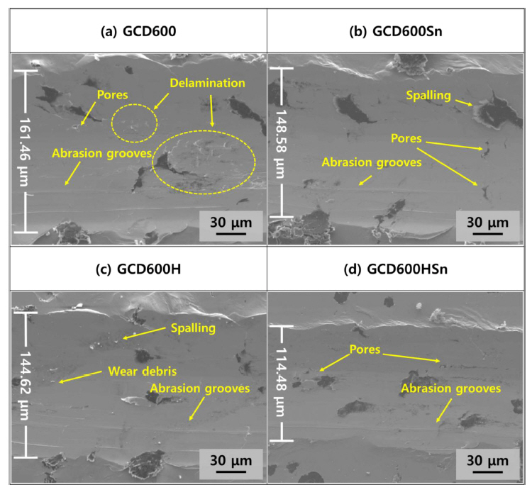
Figure 7 shows SEM images of the surface of the specimens subjected to the friction–wear test. The images revealed that GCD600 exhibited the widest abrasion width of 161.46 µm, and delamination of the soft matrix and some pores were confirmed in this specimen (Fig 7a). Furthermore, the abrasion width of the GCD600Sn (Fig 7b) was 148.58 µm, and no delamination of the soft matrix was observed, but the number of pores increased, which is consistent with the optical microscopy results (Fig 4b). In addition, a torn part was observed in the soft matrix around the nodular graphite, which could be attributed to spalling of the nodular graphite.
Compared to the GCD600 specimen, the abrasion width of the GCD600H specimen decreased to 144.62 µm due to the formation of a hard pearlite matrix (Fig 7c). In addition, no delamination of the matrix or spalling of the nodular graphite was observed in this specimen, because a hard matrix was formed, but some matrix spalling was observed, and wear debris was observed to gather around it. The spalling was assumed to occur in the relatively soft ferrite matrix that had not completely transformed into pearlite.
The GCD600HSn specimen exhibited the narrowest abrasion width of 114.48 µm (Fig 7d), and the friction between the specimen and the pins proceeded without spalling of the nodular graphite or delamination of the matrix, similar to the GCD600H. However, like GCD600Sn, the number of pores in the matrix of the GCD600HSn specimen increased. In addition, the nodular graphite in the HF–HT specimens was torn without spalling, and there was no change in the matrix surrounding the nodular graphite.
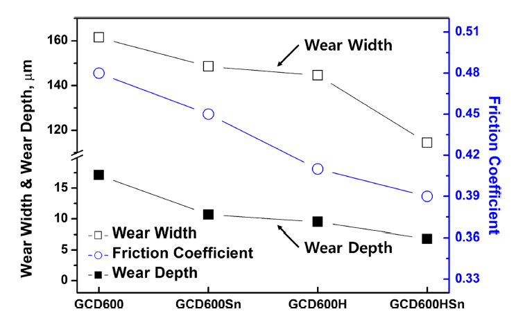
Figure 8 provides a graphical summary of the correlation between the friction coefficient, wear depth, and wear width. As described previously, the wear depth and width decreased as the surface hardness increased, which resulted in a decrease in the adhesive force between the pin and the disk, thus decreasing the average friction coefficient. This indicates that the abrasion depth and width exhibited a certain relationship with the surface hardness, which is a well-known phenomenon. As the degree of wear decreased with the increase in surface hardness, the high surface hardness enhanced the wear resistance of the nodular graphite cast iron.
4. CONCLUSIONS
In conclusion, due to the increase in the Sn content of the specimen, the chemical modification treatment not only resulted in the transformation of a part of the ferrite matrix into pearlite, but also increased the surface hardness and strength of the nodular cast iron by affecting the nodularity and the number of nodular graphite components. In addition, the addition of Sn resulted in an increase in the number of pores. HF–HT resulted in an increase in surface hardness, by promoting the transformation of most of the matrix into pearlite.
The results of the friction–wear test revealed that some parts of the matrix with a soft surface adversely affected the friction–wear properties, such as delamination inside the matrix and spalling of the nodular graphite, and the abrasion depth and width of these parts were large. In contrast, neither matrix delamination nor nodular graphite spalling occurred in the specimens with a hard matrix (GCD600H, GCD600HSn), and both the abrasion depth and width of these specimens were reduced.
In conclusion, the HF–HT method, which directly affected the matrix, was more effective at enhancing the surface hardness and friction–wear properties of the nodular graphite cast iron. Therefore, the change in the matrix had a greater effect on the improvement in friction–wear properties than the change in the nodular graphite content.