Synthesis of Porous Particles by Electrospray-Assisted Self-Assembly for Water-Repellent or Photocatalytic Surfaces
Article information
Abstract
In this study, an electrospray technique was used for the synthesis of macroporous ceramic particles, such as silica or titania, by a colloidal templating method. For this purpose, a suspension of polystyrene nanospheres was synthesized by dispersion polymerization for use as sacrificial templates. The feed solution containing a ceramic precursor and polymeric beads was injected through a metallic nozzle under a high electric field for nebulization of aerosol droplets as micro-reactors. Under ambient air conditions, the volatile components were evaporated from the droplets, and gelation of the precursor was completed simultaneously. The resulting supra-aggregates were then collected, and calcination was performed to form porous ceramic particles by removing the polymeric templates. As a demonstrative application, the porous particles of silica were deposited as a coating film for superhydrophobic surfaces with a high water contact angle larger than 150°. Furthermore, macroporous titania particles were used as photocatalytic particles in a wastewater system with first-order reaction kinetics.
1. INTRODUCTION
Porous particles have attracted tremendous attention for their wide applications, such as catalytic materials, thermal insulators, sound absorbers, electrode materials, and adsorbents [1-5]. Among the various fabrication routes of porous materials, templating approaches are considered as effective means for controlling the pore size and morphologies [6]. For the formation of mesopores and macropores, colloidal templating methods have been found to be efficient when they are combined with droplet-assisted self-assembly due to the facile and economic features of the self-assembly route [7]. Although the entire morphology of the final porous materials synthesized by droplet-assisted self-organization is mainly limited to spherical particles, the shape of the porous materials can be tuned to other geometries such as ellipsoidal particles because their shapes can be easily controlled by applying an electric field or by adjusting the drying conditions [8,9].
Thus far, the synthesis of porous particles has been studied intensively using emulsion droplets as confining geometries. Both water-in-oil and oil-in-water emulsions have been adopted as micro-reactors for the fabrication of porous particles using nanoparticles or metal alkoxides as precursor materials [10-12]. However, these approaches have the limitation that the continuous phase surrounding the droplets should be discarded as wastes after synthesis, leading to high production costs. Thus, a continuous process using aerosol droplets such as spray pyrolysis or spray drying technologies can be an efficient alternative route compared to emulsionassisted self-assembly [13-15]. The production yield and high energy cost can be considered as further research topics when industrial scale-up is considered in aerosol-based approaches.
Because the electrospray apparatus is relatively simple compared to other types of aerosol-based techniques such as spray pyrolysis and spray drying, the fabrication of functional particles by the electrospray process has been intensively studied by generating aerosol droplets under a strong electric field [16]. Similar to the electrospinning process, the electric field applied to a metallic nozzle, and the gap distance between the tip and the collector can be adjusted to control the evaporation rate of the droplets during the electrospray process. In addition to porous materials, hollow silica particles without agglomeration can be prepared using positively charged polystyrene beads and a negatively charged silica nano-colloid by adjusting the spraying conditions during the electrospray process [17]. However, a systematic study on the synthesis of porous particles is still necessary for the application of artificial surfaces with water-repellent or photocatalytic properties by electrospray-assisted self-assembly.
In the present study, porous ceramic microparticles were synthesized using polystyrene nanospheres as sacrificial templates by electrospray assisted self-assembly. For this purpose, shrinking droplets were adopted as micro-reactors to induce the gelation of ceramic precursors containing polymeric particles. Colloidal templating was then carried out for the formation of macropores by removing the polymeric beads to obtain spherically porous ceramic particles. As demonstrative applications, the porous silica particles deposited on a SUS sheet were transformed into superhydrophobic surfaces after a wet chemical treatment using a fluorine-containing silane coupling agent. In addition to silica, macroporous titania particles synthesized by the electrospray apparatus were applied as a slurry-type or film-type photocatalyst for wastewater treatment. The goals of this study were to show that the fabrication of porous ceramic particles is possible without using an expensive continuous phase and to apply those porous materials as functional surfaces.
2. MATERIALS AND METHODS
2.1. Materials and chemicals
Tetraethylorthosilicate (TEOS, 99.9%) and titanium diisopropoxide acetylacetonate (TDIP, 75 wt% in isopropanol) were used as precursors for the synthesis of macroporous silica and titania particles, respectively, and were purchased from Sigma-Aldrich. For the gelation of the precursors inside the aerosol droplets, hydrochloric acid (0.1 N) was bought from Sigma-Aldrich. To synthesize polystyrene nanospheres, styrene (99%) as a monomer and α,α’-azobis(isobutyronitrile (AIBN, 99%) as an initiator were purchased from Daejung Chemicals and Sigma-Aldrich, respectively. 2-(methacryloyloxy) ethyltrimethylammonium chloride (MTC, 72%) for use as a cationic monomer was procured from Aldrich Chemicals. Polyvinylpyrrolidone (PVP K30, Mw = 40,000) as a stabilizer was purchased from Junsei Chemicals. Ethanol (99.9%, HPLC grade) as a reaction medium was bought from Daejung Chemicals. Polyvinylpyrrolidone (PVP360, Mw = 360,000 g/mol) was used as an additive in the feed solution during electrospray or electrospinning.
For surface modification, a fluorine-containing silane coupling agent, HDFTHDTS (heptadecafluoro-1, 1, 2, 2-tetrahydrodecyl) triethoxysilane, 97%), was bought from Aldrich Chemicals. For the photocatalytic decomposition reaction, methylene blue was used as a model contaminant and purchased from Samchun Chemicals. For photocatalytic decomposition, methylene blue trihydrate was bought from Samchun Chemicals.
2.2. Synthesis of polystyrene nanospheres for templating materials
Dispersion polymerization was performed to synthesize monodisperse polystyrene nanospheres with a diameter of either 293.8 or 865.2 nm. Ethanol, as the reaction medium containing polyvinylpyrrolidone (PVP), was poured into a batch polymerization reactor at 70 ºC. A suitable amount of styrene and an aqueous solution of MTC were then added to the reactor during gentle stirring at 170 to 200 rpm according to the composition summarized in Table 1. After nitrogen purging for 1.5 hours, the initiator, AIBN, was added to the reactor for polymerization for 19 hours. The resulting suspension was filtered and re-suspended in fresh ethanol with a solid concentration of 15 wt%.
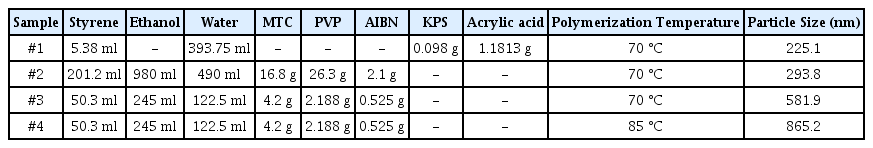
Synthesis conditions of polystyrene latex suspension by dispersion polymerization.
For the synthesis of smaller particles with a diameter of 225.1 nm, emulsion polymerization was conducted using water as a reaction medium. Styrene and acrylic acid were used as the monomer and comonomer, and the polymerization was initiated by KPS according to the composition in Table 1. The resulting particles were redispersed in fresh ethanol by repeated centrifugation.
2.3. Electrospray-assisted self-assembly for porous silica particles and superhydrophobic surfaces
The feed solution for the electrospray process was prepared by resuspending the polystyrene nanospheres in ethanol with a proper solid concentration (15 wt%, 7 ml) by centrifugation and sonication. TEOS (2 ml) and aqueous hydrochloric acid (0.01 N, 0.67 ml) were then added to the polymeric dispersion under stirring. Using a syringe pump (AL-4000, World Precision Instruments), the resulting feed solution was injected through a metallic nozzle (0.2 mm ID, 0.4 mm OD, NanoNC) under a constant feed rate (10 μl/min). Simultaneously, a high voltage power supply (NNC-HV60, NanoNC) was operated at 12 kV for the atomization of the droplets containing the precursor materials. The resulting droplets were evaporated in an atmospheric environment and collected on a flat-type collector (SUS sheet). The distance between the nozzle and the collector was maintained as 25 cm. Calcination was then performed using a box furnace (Hantech, M13P) at 500 °C for 5 hours to synthesize macroporous silica microparticles coated on the SUS sheet.
The SUS sheet coated with macroporous silica microparticles was treated with a fluorine-containing silane coupling agent by dipping the sheet inside a methanol solution containing 2 vol% of HDFTHDTS for 2 hours. The treated film was then dried at room temperature for several days to measure the water contact angle.
2.4. Electrospray-assisted self-assembly for porous titania particles and photocatalytic surfaces
The same method used for the macroporous silica microparticles was adopted for the synthesis of the macroporous titania microparticles by an electrospray technique except that TDIP was used as a precursor instead of TEOS. After electrospraying, the resulting supraaggregates were collected from the SUS sheet, and calcination was performed to produce porous titania particles for further application. The resulting macroporous titania microparticles were resuspended in an aqueous medium with a fixed concentration of 0.0002 g/ml. The aqueous solution with dissolved methylene blue was then mixed with a titania suspension at a 1:1 volume ratio, followed by equilibration for 30 minutes under a dark condition. For the photocatalytic reaction, UV light was irradiated using eight UV lamps (F10T8 BLB, 10 W, peak wavelength at 352 and 369 nm, Sankyo Denki). During the reaction, a small amount of sample was collected for the measurement of the dye concentration using a UV-visible spectrometer (Optizen Pop) for regular time intervals.
2.5. Characterization of the porous ceramic particles and functional surfaces
The particle size and distribution of the polystyrene suspension were measured using a particle size analyzer (ZETA PLUS, Marlvern Instruments). The morphologies of the porous ceramic particles were observed using a field emission scanning electron microscope (FE-SEM, Hitachi-S4700). The compositions of the powder materials synthesized by electrospray were analyzed by a Nicolet FT-IR spectrometer (Thermo Fisher Scientific co. Ltd). The composition of the fluorinated coating film was measured by XPS analysis (ULVAC-PHI 5000 VersaProbe, Phi(Φ)). The static contact angle of a water droplet was measured using a contact angle measurement system (Phoenix-Mini, Surface & Electro-Optics Co. Ltd). The crystallinity of the porous titania particles was analyzed using a powder X-ray diffraction technique (D/MAX-2200/PC).
3. RESULTS AND DISCUSSIONS
3.1. Electrospray-assisted self-assembly strategy for porous ceramic particles
In this study, the self-assembly scheme using aerosol droplets generated by the electrospray apparatus was applied for the synthesis of spherically porous ceramic particles composed of silica or titania. The set-up of the electrospray process is schematically shown in Fig 1(a), which shows the metallic tip connected with a high voltage power supply for the generation of the aerosol droplets. By supplying the proper voltage, the feed solution from the metallic nozzle was atomized to the atmospheric environment, causing evaporation of the volatile medium until the attachment of the resulting self-assembled particles to the flat-type collector. Figure 1(b) shows the formation process of the porous ceramic particles using the electrospray apparatus from tiny aerosol droplets as micro-reactors by self-organization of the precursors and templates for the formation of air cavities or macropores. To fabricate porous particles with spherical morphologies, metal alkoxide and polystyrene nanospheres were utilized as precursor materials for the ceramic component and organic templates, respectively. Both materials were dispersed and mixed in a volatile organic solvent, ethanol, with a small amount of hydrochloric acid for the gelation reaction. By applying the electrospray method, the mixed dispersion was atomized as tiny droplets, which were shrunken during evaporation of the volatile medium to induce inward capillary pressure for self-organization inside the droplets. The resulting self-assembled supra-aggregates were collected on a metallic sheet, followed by calcination of the composite particles for the formation of spherically porous ceramic particles by the removal of the polymeric particles.
Schematic figure for the fabrication of (a) porous spherical ceramic particles by electrospraying and (b) droplet-assisted self-assembly process of porous particles from tiny droplets generated by electrospraying.
3.2. Fabrication of porous silica particles by electrospray-assisted self-assembly
Figures 2(a) and 2(b) show the morphologies of the monodisperse polystyrene nanospheres synthesized by dispersion polymerization, and the supra-aggregates fabricated by the electrospray apparatus using the polymeric particles and TEOS as ceramic precursors. The inset image in Fig 2(a) shows the size distribution of the polystyrene nanospheres measured by a dynamic light scattering apparatus. The distribution of the building block particles is monodispersed with an average diameter of 327.2 nm, which coincides well with the SEM observation from Fig 2(a). Using these monodisperse spherical polystyrene nanospheres as building block particles, the supra-aggregates were produced by self-organization inside the shrinking aerosol droplets, as seen in the SEM image of Fig 2(b). The interstitial voids between the polystyrene nanospheres in the supra-aggregates are filled with the hydrolyzed component of TEOS, indicating that composite particles could be produced inside the evaporating droplets acting as micro-reactors. As shown in Fig 2(b), the size distribution of the supraaggregates is polydispersed, implying that the original aerosol droplets produced from the electrospray apparatus are also polydispersed.
Scanning electron microscope image of (a) monodisperse polystyrene nanospheres used for the formation of macropores as templates and (b) the self-assembled supra-aggregates of the polystyrene nanospheres and TEOS. Scale bar indicates 1 μm. The inset figure in (a) contains the size distribution of the monodisperse polystyrene nanospheres.
Figure 3(a) shows a SEM image of the macroporous silica microparticles produced from the sample shown in Fig 2(b) after calcination. During the heat treatment, the polystyrene nanospheres were removed by thermal decomposition, leaving a number of air cavities as macropores in the silica microparticles. Because the hydrolyzed component from the supra-aggregates can be transformed into inorganic silica during calcination, ceramic particles with high porosity were fabricated, as seen in the magnified SEM image of Fig 3(a). The morphologies of the porous particles fabricated using a feed solution without PVP360 in Fig 3(a) were observed as spheroids or deformed spheres (Feed #1 in Table 2). Similar morphologies were observed for the sample from the feed solution with PS particles and PVP360 dispersion at a volume ratio of 29:1 (Feed #2 in Table 2), as seen in the SEM image of Fig 3(b). However, the morphologies of the particles were changed as porous spheroids with fragments of fibers, when the amount of PVP360 was increased to a volume ratio of 9:1 (Feed #3 in Table 2), as seen in the SEM image of Fig 3(c).
(a) SEM image of macroporous silica microparticles fabricated by electrospraying. No PVP was added in feed solution before electrospray. Scale bar indicates 1 μm. (b) SEM image of macroporous silica microparticles fabricated by electrospraying. 0.1-ml PVP dispersion in ethanol was added in feed solution composed of 2.9-ml PS particle dispersion in ethanol mixed with TEOS and HCl before electrospraying. Scale bar indicates 10 μm. (c) SEM image of macroporous silica microparticles fabricated by electrospraying. 0.25-ml PVP dispersion in ethanol was added in feed solution composed of 2.25-ml PS particle dispersion in ethanol mixed with TEOS and HCl before electrospraying. Scale bar indicates 10 μm. (d) SEM image of macroporous silica fibers fabricated by electrospinning.
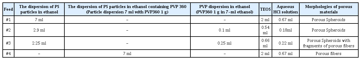
The composition of feed solution in electrospray and electrospinning process.
A complete transformation of shapes was observed when the amount of PVP360 was further increased, as seen in the SEM image of Fig 3(d), which shows macroporous silica fibers. Under this condition, the term electrospinning is more appropriate than electrospray because the amount of PVP360 was increased to maintain a sufficient viscosity for the elongation of the spinnerets from the nozzle to form fibrous materials (Feed #4 in Table 2). Thus, it is evident that the amount of the additive PVP360 has an important role for controlling the morphologies of the final porous materials because the protrusion of droplets or spinnerets from the metallic nozzle can be tuned by changing the amount of PVP to adjust the viscosity of the feed solution [18]. When the viscosity of the feed solution was low (Feed #1 to #2), electrospray was observed, resulting in the formation of porous spheroids. However, a feed solution with a relatively high viscosity (Feed #4) resulted in the fabrication of porous fibrous materials, indicating that electrospray is no longer expected. In the intermediate condition (Feed #3), a mixture of porous spheroids and fragments of porous fibers was observed, shown in Fig 3(c).
The composition of the macroporous silica particles synthesized by electrospray was confirmed by FT-IR analysis from the graph of Fig 4(a). The FT-IR spectrum of the supraaggregates shown in Fig 2(a) is also contained in the graph of Fig 4(a), showing that the characteristic peaks derived from the polystyrene nanospheres were detected before calcination. The characteristic peak of the polystyrene nanospheres at 1,600.8 cm-1 is due to the stretching vibration of the benzene ring, which disappeared after the thermal decomposition of the polymeric particles [19]. In Fig 4(a), the dotted line indicates the FT-IR spectrum of the sample after calcination, which contains the characteristic peaks of SiO2 at 800 and 1,110 cm-1 [20]. Thus, it can be concluded that the gelation of TEOS by hydrochloric acid inside the aerosol droplets was successfully induced, indicating that the transformation into silica was successful after heat treatment at 500 °C. The weight loss during heating from room temperature to 800 °C was recorded by TGA and is included in Fig 4(b). Due to the calcination of the polymeric templates and organics originating from the metal alkoxide precursor, about 96% of the initial materials were removed at 500 °C, indicating that highly porous macroporous silica particles were obtained by electrospray-assisted self-organization and subsequent heat treatment.
(a) FT-IR spectrum of self-assembled supra-aggregates of polystyrene nanospheres and TEOS. The spectrum of the sample after calcination (macroporous silica) is also included in the same graph. (b) TGA result of self-assembled supra-aggregates of polystyrene nanospheres and TEOS.
3.3. Superhydrophobic surfaces using porous silica particles
As an application of the macroporous silica particles synthesized by electrospray-assisted self-assembly, superhydrophobic surfaces were fabricated such that the static contact angle of a water droplet was larger than 150° shown in Fig 5. The contact angle of the water droplet was measured as 76° on the surface of the metallic collector made of a SUS sheet, as seen in the photograph of Fig 5(a). Although the result is not reproduced here, the water droplet spread rapidly on the SUS plate coated with the macroporous silica microparticles without the treatment using the fluorine-containing silane coupling agent. For the fabrication of superhydrophobic surfaces, electrospray-assisted self-assembly was carried out on the SUS sheet for the deposition of macroporous silica microparticles, and the resulting coating layer was modified using a fluorine-containing silane coupling agent, HDFTHDTS. Before modification with HDFTHDTS, the contact angle of the water droplet could not be measured because the water droplet was spread on the coating film of the macroporous silica particles, indicating that a superhydrophilic property was obtained due to the hydroxyl groups on the silica particles after electrospray-assisted deposition of the porous silica. After the hydrophobic treatment using the silane coupling agent on the porous coating film, the static contact angle of the water droplet was increased remarkably due to the lotus effect, as seen in the photograph of Fig 5(b). The measured value of the contact angle, 157.4°, was higher than 150°, indicating that the surface of the SUS sheet could be functionalized with a superhydrophobic property. Because the deposited film is composed of spherically porous particles with spherical macropores, the coating layer can be interpreted as a hierarchical porous structure with abundant air cavities. When the fluorine-containing silane coupling agent is attached covalently on the porous layer, the coating film can be coated as hydrophobic molecules. Thus, a lotus effect can be expected from the coating layer, which can be confirmed by the analysis of the contact angle shown in Fig 5. Because the contact angle of the water droplet on the surface of the bare SUS sheet was just 76°, the contact angle increased by about 107% after the deposition of the porous particles and fluorine treatment. This water-repellent surface with a superhydrophobicity can be adopted for important industrial applications such as self-cleaning surfaces or icephobic coatings for blades and airplanes.
(a) The photograph of SUS sheet without coating and surface treatment. The photograph of water droplet on the plate is also included with static contact angle. (b) The photograph of SUS sheet coated with macroporous silica particles. The photograph of water droplet on the coating film after fluorine treatment is also included in the same figure. (c) FT-IR spectrum of coating film using macroporous silica particles by electrospraying on SUS sheet before and after fluorine treatment. The inset figure presents the magnified spectrum of surface-modified porous silica film (the wavenumber from 550 to 1,300 cm-1). (d) XPS analysis results of the coating film composed of the porous silica particles after fluorine treatment.
To confirm the hydrophobic surface treatment using the fluorine-containing silane coupling agent, FT-IR spectra were measured for the coating film composed of macroporous silica particles on a SUS sheet before and after the surface treatment. Figure 5(c) contains the resulting spectrum, which shows that slightly different peaks appeared at wavenumbers such as 610, 730, and 1,250 cm-1 due to the functional groups CF, CF2, and CF3 after the surface treatment using HDFTHDTS, indicating that the fluorine groups were attached to the surface of the porous silica particles [21]. The surface composition of the fluorinated porous film was also confirmed by XPS analysis, as seen in the graph of Fig 5(d), which contains the XPS spectrum for the 1-Fs peak as an inset figure. The atomic concentration of fluorine was estimated to be 24.51%, as summarized in Table 3, suggesting that the fluorination was successfully conducted by wet chemical treatment. In addition to fluorine, oxygen and silicon were also confirmed by the XPS data, indicating that porous silica particles were coated on the SUS sheet shown in Figure 5(d). Fe element was also confirmed by the XPS data, implying that some portion of the SUS sheet was not completely covered with the porous silica. The carbon element confirmed by the XPS data could originate from the organic material, the fluorine-containing silane coupling agent.
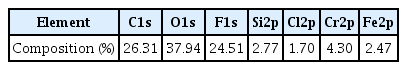
The atomic concentration of the fluorinated coating film measured by XPS analysis.
As shown in Fig 6, the contact angle of the water droplet on the SUS sheet was measured as a function of the size of the macropores in the coating film by changing the size of the polystyrene nanospheres during the electrospray process. Regardless of the size of the macropores, the surface of the coating film could be maintained as a superhydrophobic layer because the contact angle was larger than 150° as the diameter of the macropores was changed from 225.1 to 865.2 nm. Thus, it is thought that the Cassie-Baxter state could be retained because the size of the spherical air cavities of the porous film was larger than 200 nm, indicating that the penetration of water droplets through the porous surfaces was not possible.

The change of the static contact angle of water droplets on SUS sheet as a function of the size of macropores.
3.4. Synthesis of porous titania particles by electrospray-assisted self-assembly
Thus far, the synthesis of macroporous silica microparticles by aerosol-assisted self-assembly was discussed using the electrospray apparatus for the generation of droplets as micro-reactors. To produce porous ceramic particles, unlike silica, another precursor, TDIP could be adopted for the synthesis of macroporous titania microparticles by the electrospray technique. Because the titania precursor TDIP is protected by acetylacetone, the hydrolysis and condensation rate can be easily controlled unlike the conventional titanium alkoxide precursors. For instance, titanium isopropoxide can be hydrolyzed by the humidity in the air, implying that it may not be adequate for the electrospray technique.
Figures 7(a) and 7(b) present SEM images of the porous titania microparticles synthesized by aerosol-assisted self-organization of polystyrene nanospheres and TDIP as the sacrificial templates and ceramic precursor, respectively. For the generation of the tiny aerosol droplets, nebulization by electrospraying was adopted to atomize and evaporate the feed solution. As shown in the SEM image, porous titania microparticles with a number of air cavities were produced after calcination of the composite microparticles collected on the SUS plate.
Scanning electron microscope image of macroporous titania particles fabricated by electrospraying.
To confirm the composition of the porous titania particles, FT-IR spectra were measured for the sample before and after the heat treatment shown in the graph of Fig 8(a). After calcination, several characteristic peaks of the polystyrene nanospheres from the supra-aggregates disappeared due to the removal of the polymeric particles, and the remaining peaks coincided well with the results of pure TiO2. From the magnified absorption peaks in the inset figure, the Ti-O vibration at 594 and 621 cm-1 was confirmed, indicating that titania particles were successfully fabricated after the calcination [22].
(a) FT-IR spectrum of self-assembled supra-aggregates of polystyrene nanospheres and TDIP. The spectrum of the sample after calcination (macroporous titania) is also included in the same graph. The inset figure contains the magnified FT-IR spectrum of macroporous titania particles after calcination. (b) micro-crystalline XRD analysis results of porous titania film coated on SUS sheet.
The XRD analysis results of the coating film composed of the macroporous titania particles on the SUS sheet are shown in the graph of Fig 8(b), which shows the anatase titania peaks [23]. Although some other peaks also were observed due to impurities such as the adhesive, the supra-aggregates formed by electrospraying were transformed into inorganic titania particles after the removal of the polymeric beads during thermal decomposition.
Because the energy bandgap of titania depends on the crystallinity of the material, it is important to confirm the anatase crystal structure of the macroporous titania powder prepared by electrospray shown in Figure 8(b). For anatase titania, the bandgap energy is 3.2 eV, whereas the value of the rutile phase is 3.0 eV [24]. Thus, UV light with a wavelength smaller than 388 nm should be illuminated onto our porous titania powder with the anatase phase for photocatalytic applications. Though the bandgap energy can be measured by calculation from the diffuse reflectance spectrum, we adopted the well-known literature value of 3.2 eV in our experiments [25].
3.5. Photocatalytic decomposition of an organic dye using the porous titania particles or photocatalytic surfaces
As another application of the porous ceramic particles synthesized by electrospray-assisted self-assembly, the photocatalytic decomposition of a model contaminant, methylene blue, was carried out using the macroporous titania microparticles shown in Fig 7 as the photocatalyst. The supra-aggregates were collected from the SUS sheet after the electrospray process, and the resulting powder material was converted into macroporous titania microparticles after calcination at 500 °C. The porous titania particles were then resuspended in an aqueous medium, which contained methylene blue at a known concentration. As shown schematically in Fig 9(a), the photocatalytic decomposition reaction was performed using a slurry-type reactor during mild stirring under 8 UV lamps as the light source. Figure 9(b) presents the change in the concentration of methylene blue as a function of the UV irradiation time in the slurry-type reactor. Regardless of the initial dose of methylene blue, the concentration of the dye molecules decreased monotonically with an increasing UV irradiation time during the decomposition reaction. As the initial dose of methylene blue decreased, the reduction rate of the concentration of the contaminant increased under the UV irradiation. For instance, the dimensionless concentration (C/C0) of the dye molecules decreased to about 0.1 after UV irradiation for 60 minutes when 0.005 mg/ml of methylene blue was dissolved as the initial dose in the reactor. This result shows that wastewater treatment using the porous titania particles as a photocatalyst synthesized by the electrospray technique was successful.
(a) Schematic figure of slurry-type photocatalytic reactor using porous titania particles as a photocatalyst. (b) The dimensionless concentration (C/C0) of methylene blue as a function of UV irradiation time in a batch-type slurry reactor. The initial dose of methylene blue was adjusted from 0.000005 to 0.00002 g/ml. (c) semi-log plot of C/C0 as a function of UV irradiation time. (d) The change of apparent rate constant of photocatalytic decomposition reaction of methylene blue as a function of the initial concentration of the model contaminant.
For the interpretation of the decomposition reaction using the slurry-type photocatalytic reactor, first-order kinetics was assumed, and the semi-log plot shown in Fig 9(c) was obtained from the graph in Fig 9(b). From the regression line of the resulting graph in Fig 9(c), the apparent rate constant, kapp, was estimated using the following first-order kinetics [26].
Here, C and t denote the measured concentration of the methylene blue using the absorbance at 666 nm obtained by a UV-visible spectrometer and UV irradiation time, respectively. The experimental data in the graph of Fig 9(c) fitted well with the regression lines, implying that the photocatalytic decomposition reaction can be interpreted by Langmuir-Hinshellwood kinetics [27,28]. The apparent rate constant increased from 0.0099421 to 0.0424 min-1 by decreasing the initial dose of the contaminant, as summarized in Table 4 and in the graph of Fig 9(d). When the porous titania particles synthesized from emulsion droplets were used as the photocatalyst, the estimated apparent rate constant had a similar value, indicating that electrospray can be adopted for the fabrication of porous photocatalytic particles in addition to the emulsion-assisted self-assembly strategy [29]. The values of the apparent rate constant in this study are also comparable to that of the macroporous anatase titania particles synthesized by spray pyrolysis, which was used for the decomposition of rhodamine B [30]. Thus, we believe that our electrospray approach also can be considered efficient and economical for the fabrication of porous materials.

The apparent rate constant kapp of porous titania particles fabricated by an electrospray technique for the decomposition reaction of methylene blue. A slurry-type reactor was used for photocatalytic decomposition.
The slurry-type reactor using porous titania particles as a photocatalyst is advantageous in that the large surface area and high porosity of the particles can be exploited for the adsorption and decomposition of organic contaminants. Because the size of the porous titania particles is in the range of micrometers, the particles can settle due to gravitational force after a few hours. However, the separation of the photocatalyst from the resulting purified water should be done by a more convenient process using a film composed of porous titania particles, as described schematically in Fig 10(a). The coating film fabricated by electrospraying can be immersed in an aqueous methylene blue solution, and photocatalytic decomposition can be conducted by UV irradiation. Figure 10(b) presents the change in the dimensionless concentration (C/C0) as a function of the UV irradiation time. As shown in the graph, C/C0 decreased to about 0.45 after UV irradiation for 60 minutes, indicating that the removal rate of the film-type photocatalyst is less effective than that of a slurry-type photocatalytic reactor. Because the generation rate of the active radicals from water can be reduced from the photocatalytic film immersed in wastewater, a relatively smaller apparent rate constant (0.0108 min-1) can be estimated from the graph in Fig 10(c) compared to the result using a slurry-type reactor (0.0424 min-1). When the concentration of methylene blue was increased to 0.00001 g/ml, the rate constant decreased to 0.0019 min-1 due to the limited photocatalytic activity of the porous titania film summarized in Table 5. Thus, the apparent rate constant increased with a decreasing initial concentration of the methylene blue for the film-type photocatalytic reactor like for the results from the slurry-type photocatalytic reactor.
(a) Schematic figure of batch-type photocatalytic reactor using porous titania film as photocatalyst. (b) The dimensionless concentration (C/C0) of methylene blue as a function of UV irradiation time. The film composed of porous titania particles was immersed inside the batch-type reactor. The initial dose of methylene blue was 0.000005, 0.0000075, and 0.00001 g/ml. (b) semi-log plot of C/C0 as a function of UV irradiation time.

The apparent rate constant kapp of porous titania particles fabricated by electrospray technique for the decomposition reaction of methylene blue. A film-type reactor was used for photocatalytic decomposition.
Among the experimental results in Figs 9 and 10, the photocatalytic decomposition rate using the same initial concentration of methylene blue, 0.000005 g/ml, can be considered to compare the efficiency of the slurry and filmtype photocatalytic reactors. In this experimental condition, the apparent rate constants of the slurry and film-type reactors were estimated as 0.0424 and 0.0108 min-1, respectively, as summarized in Tables 4 and 5. Thus, a faster decomposition of methylene blue was observed by the slurry-type photocatalytic reactor compared to the film-type reactor because a larger surface area of catalytic particles can be expected to generate active chemical species under UV irradiation. In contrast, only a limited contact area from the two-dimensional film with an aqueous medium can be expected, causing a slower decomposition of methylene blue shown in Fig 10.
Although photocatalytic decomposition of dye using a twodimensional photocatalytic film may not be advantageous compared to a slurry-type photocatalytic reactor in this study, the two-dimensional structure can be applied to photocatalytic water splitting for hydrogen production [31,32]. Recently, bandgap engineering of photocatalytic materials has been actively conducted using various kinds of materials including graphene, chalcogenides, and carbon nitrides. The heterojunction structures of these materials are advantageous to facilitate charge transfer and photocatalytic activity of two-dimensional photocatalysts. Thus, more studies using two-dimensional photocatalysts are still necessary to focus on the interfacial engineering of photocatalytic films, which can be considered in future works.
Thus far, the synthesis of porous ceramic particles by electrospray-assisted self-assembly was discussed by emphasizing the applications of superhydrophobic surfaces and wastewater treatment by photocatalytic decomposition. Droplet-assisted synthesis of functional particles also can be carried out effectively using a complex fluid system such as in the case of emulsions [33,34]. However, the aerosol-based self-organization method using the electrospray or electrospinning apparatus can be more advantageous for an economic synthesis of porous ceramic particles with various functionalities because an expensive continuous phase is required in emulsion-assisted self-assembly approaches [35]. Compared to the relatively large scale and complicated equipment in spray pyrolysis reactors or spray dryers for the generation of aerosol droplets, the electrospray or spray forming technique can be used in a relatively straightforward manner, which is useful for laboratory-scale tests and further scale-up [36]. To enhance the production yield during the electrospray process, multi-nozzle systems can be considered for multiple protrusions of droplets, which can be considered as new research.
4. CONCLUSIONS
In this study, porous ceramic particles were synthesized from aerosol droplets as micro-reactors using an electrospray apparatus as a droplet generation system. For the formation of macropores, polystyrene nanospheres were used as sacrificial templates, and evaporation-driven self-assembly of the ceramic precursors was induced inside the shrinking droplets during the evaporation of the volatile components in the air. The deposition of porous silica particles on a SUS sheet was conducted by an electrospray process as an application for a superhydrophobic coating layer by wet chemical treatment using a fluorine-containing silane coupling agent. The resulting porous surfaces showed an extremely high contact angle for water droplets and thus, are applicable as water-repellent surfaces. In addition to silica, macroporous titania particles were also synthesized by electrospray-assisted self-assembly using TDIP as a ceramic precursor. The resulting porous titania particles were used as a photocatalyst to remove the organic dye in an aqueous medium for application to wastewater treatment.
Acknowledgements
This research was supported by the Basic Science Research Program through the National Research Foundation of Korea (NRF) funded by the Ministry of Science, ICT & Future Planning (NRF-2017R1C1B5017174), the Priority Research Centers Program through the National Research Foundation of Korea (NRF) funded by the Ministry of Education (NRF-2017R1A6A1A03015562), and the Industrial core technology development program (10077545, Development of icephobic coating materials for extreme environment) funded by the Ministry of Trade, industry & Energy (MI, Korea).
Notes
Nomenclature
C = concentration of methylene blue [g/ml]
t = UV irradiation time [min]
kapp = apparent rate constant [min-1]