1. INTRODUCTION
The ongoing development of eco-friendly and cost-effective thermoelectric materials has recently attracted increasing attention [1,2]. Several interesting candidates with promising electrochemical properties have been identified from the Cu-Sb-Se ternary chalcogenides. One such candidate, permingeatite (Cu3SbSe4), belongs to the tetragonal crystal structure with the space group I 4 ¯ 2 m
A unit cell of Cu3SbSe4 contains four times more atoms than that of ZnSe [6]. Cu3SbSe4 has a crystal structure comprised of one-dimensional Sb-Se arrays of inserted SbSe4 tetrahedrons and three-dimensional Cu-Se frameworks of distorted CuSe4 tetrahedrons [5]. The Sb-Se bond lengths are greater than the Cu-Se bond lengths, and the CuⅠ-Se bond lengths are different than the CuII-Se bond lengths. These bonding differences increase the anisotropy of phonon scattering and charge transport and affect the thermal and electrical properties of the material [5]. Cu3SbSe4 has been considered as a promising thermoelectric material because of its large carrier effective mass (~1.1 mo) and narrow direct bandgap (0.13–0.42 eV) [3,6]. Nevertheless, to become a viable thermoelectric material, systematic doping studies need to be conducted to address its high electrical resistivity and high thermal conductivity [3].
The effect of dopants on the thermoelectric performance of permingeatite has been investigated in previous studies. For example, Zhao et al. [7] obtained a ZT of 0.54 at 650 K for Cu3Sb0.985Ga0.015Se4, whereas Li et al. [8] reported a ZT of 0.58 at 600 K for Cu3Sb0.97Al0.03Se4. Furthermore, Chang et al. [9] reported a ZT of 0.7 at 640 K for Cu3Sb0.96Ge0.04Se4, while Li et al. [10] reported a ZT of 0.7 at 600 K for Cu3Sb0.98Bi0.02Se4.
Because the ionic radius of Sn4+ (69 pm) is similar to that of Sn5+ (60 pm) and because Sn contains one less valence electron than Sb, it is reasonable to assume that Sn is a great acceptor for Cu3SbSe4; previously reported studies have confirmed this notion. For example, Wu et al. [11] synthesized Cu3Sb0.98Sn0.02Se4 by a wet chemical reaction using organic precursors and a hot pressing (HP) method, and reported a ZT of 0.48 at 575 K. Yang et al. [5] prepared Cu3Sb0.975Sn0.025Se4 by encapsulated melting (at 773 K for 24 h) and annealing (at 723 K for 24 h), and reported a ZT of 0.75 at 730 K. Li et al. [12] synthesized Cu3Sb0.98Sn0.02Se4 by co-precipitation and HP, and reported a ZT of 1.05 at 690 K. Bhardwaj et al. [13] prepared Cu3Sb0.985Sn0.015Se4 by encapsulated melting (at 773 K for 148 h) and spark plasma sintering, and reported a ZT of 1.1 at 623 K. Prasad et al. [14] prepared Cu3Sb0.98Sn0.02Se4 by annealing (at 723 K for 96 h) pellets made of pressed powder, and reported a ZT of 0.12 at 374 K. Finally, Wei et al. [15] synthesized Cu3Sb0.98Sn0.02Se4 by mechanical alloying (MA) at 450 rpm for 10 h under Ar/N2 atmosphere and spark plasma sintering, and reported a ZT of 0.70 at 673 K.
In our previous study [16], we successfully prepared an undoped permingeatite (Cu3SbSe4) via a solid-state synthesis consisting of MA (350 rpm, 12 h) and HP (573 K; 2 h and 70 MPa). Because the synthesized Cu3SbSe4 exhibited a low ZT of 0.39 at 623 K, we examined the BⅣ-group elements, such as 14Si, 32Ge, and 50Sn, to determine a suitable dopant to improve its thermoelectric performance. In this study, Sn-doped permingeatites Cu3Sb1-ySnySe4 (0 ≤ y ≤ 0.08) were synthesized via MA-HP processes, and their thermoelectric properties were evaluated.
2. EXPERIMENTAL PROCEDURE
To synthesize Cu3Sb1-ySnySe4 (y = 0, 0.02, 0.04, 0.06, and 0.08), we first stoichiometrically weighed powders of Cu (purity 99.9%, < 45 μm, Kojundo), Sb (purity 99.999%, < 150 μm, Kojundo), Sn (purity 99.999%, < 35 μm, LTS), and Se (purity 99.9%, < 10 μm, Kojundo). The MA process consisted of grinding these powders together in a planetary ball mill (Fritsch, Pulverisette 5). The mixed powders were then sintered by HP using a graphite die. The MA-HP process conditions for permingeatite synthesis have been previously reported [16].
Phases were analyzed by X-ray diffraction (XRD; Bruker, D8-Advance) with Cu Kα. Diffraction peaks and angles were measured for 2θ = 10–90° at a scanning step of 0.02° and scanning speed of 0.4 s/step. Lattice constants were calculated via Rietveld refinement (using the TOPAS software). The microstructure of the specimens was observed by scanning electron microscopy (SEM; FEI, Quanta400) using the backscattered electron (BSE) mode. Elemental line scans and maps were analyzed by energy dispersive spectrometry (EDS; Bruker, XFlash4010) using the following energy levels: Cu K-series, Sb L-series, Sn L-series, and Se K-series. Charge transport parameters were estimated by measuring the Hall effect using the van der Pauw method (Keithley 7065). Thermoelectric properties were examined at temperatures from 323 to 623 K. Thermal conductivity was calculated from specific heat, density, and thermal diffusivity measured by TC-9000H (Advance Riko) equipment using the laser flash method. Electrical conductivity and Seebeck coefficient were simultaneously measured using a ZEM-3 (Advance Riko) system with the four-probe method. Finally, the power factor and ZT were also calculated.
3. RESULTS AND DISCUSSION
Figure 1 presents the XRD patterns of the Sn-doped permingeatite Cu3Sb1-ySnySe4. All the diffraction peaks match the standard diffraction pattern for permingeatites (ICDD PDF# 01-085-0003). This confirms the existence of only a single phase with a tetragonal structure. Wu et al. [11], Li et al. [12], and Bhardwaj et al. [13] reported that diffraction peaks of permingeatites without secondary phases were not significantly influenced by low levels of Sn doping (y ≤ 0.02) at the Sb sites. In contrast, in the proposed study, the diffraction peaks shifted to lower angles as a result of doping with Sn (y ≤ 0.08). The lower angles indicate lattice expansion. The calculated lattice constants are summarized in Table 1. As the Sn doping increased, a- and c-axis increased from 0.56488 to 0.56525 nm and 1.12434 to 1.12520 nm, respectively. This confirms that Sn was successfully substituted at the Sb sites. Yang et al. [5] reported that a- and c-axis of Cu3Sb1-ySnySe4 (y = 0, 0.025, and 0.05) increased with increasing Sn content, and the lattice expanded because the ionic radius of Sn4+ (69 pm) is larger than that of Sn5+ (60 pm).
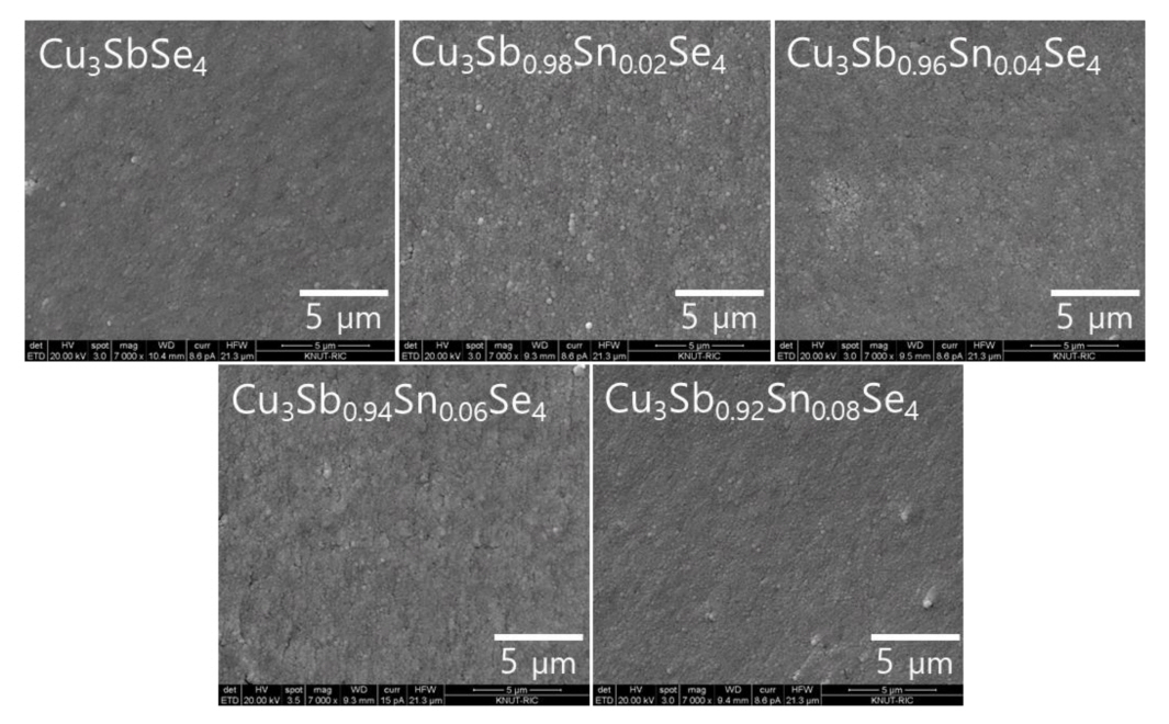
Figure 2 shows the fractured surfaces (SEM images) of our synthesized Cu3Sb1-ySnySe4 samples. As shown in Table 1, the samples have relative densities of 97.2%–98.5% compared to the theoretical density (5.82 gcm-3) for permingeatites [17]. Secondary phases were not observed, and microstructure did not change significantly with an increase in the Sn content.
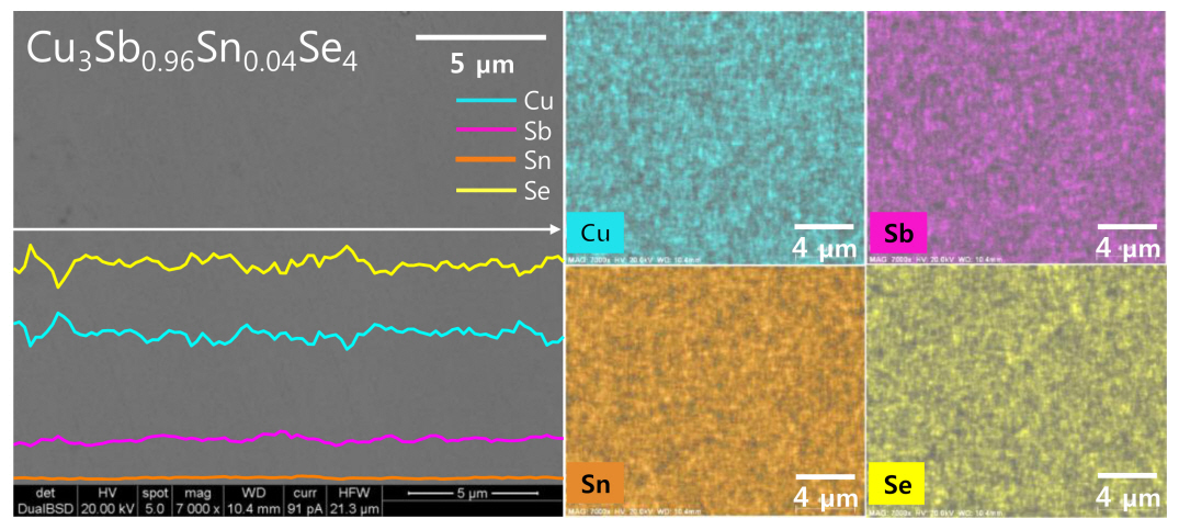
Figure 3 presents the BSE-SEM image with EDS line scans and maps of Cu3Sb0.96Sn0.04Se4. The matrix is a single permingeatite phase without secondary phases, which is consistent with the XRD results shown in Figure 1. Each constituent element is homogeneously distributed, and the elemental line scans and maps confirm the uniform distribution of the low Sn content. The actual compositions are similar to their corresponding nominal compositions, as shown in Table 1. However, given the low levels of Sn involved, there is a possibility of analysis error for this data.
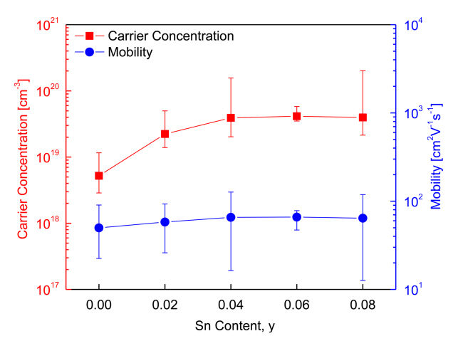
Figure 4 shows the charge transport parameters of Cu3Sb1-ySnySe4. As can be observed, as the Sn content increased, the carrier concentration increased, but mobility did not vary significantly. Specifically, the carrier concentration and mobility of intrinsic Cu3SbSe4 were 5.2 × 1018 cm-3 and 50 cm2V-1s-1, respectively, whereas those of the Sn-doped specimens (y = 0.02–0.08) increased to (2.2–4.1) × 1019 cm-3 and 58–66 cm2V-1s-1, respectively. Studies based on the carrier concentration and mobility of doped Cu3SbSe4 have been reported previously. For example, Yang et al. [5] reported a carrier concentration of 7.5 × 1018 cm-3 and mobility of 41 cm2V-1s-1 for Cu3SbSe4, but Sn-doped specimens (y = 0.025–0.05) showed a significantly increased carrier concentration of (6.3–7.8) × 1019 cm-3 and slightly decreased mobility of 35–31 cm2V-1s-1. The slight decrease in mobility was attributed to the increased electron scattering induced by lattice distortion and ionized scattering centers.
Similarly, Wei et al. [15] reported that Sn doping (y = 0.01– 0.04) on Cu3SbSe4 increased the carrier concentration from 5.0 × 10¹⁹ to 2.1 × 1020 cm-3, but reduced mobility from 45 to 35 cm2V-1s-1 because of acoustic phonon scattering. Brooks et al. [18] suggested that for non-degenerate semiconductors, mobility decreases with an increase in carrier concentration; this contradicts the findings of our study, where an increase in Sn doping was associated with an increase in carrier concentration, as well as a slight increase in mobility.
Figure 4 also shows that the measured Hall coefficients lie within the acceptable error range and that the Sn doping causes a transition in the samples from non-degenerate semiconductor to degenerate semiconductor. Suzumura et al. [19] explained that both carrier concentration and mobility could be increased by doping with degenerate semiconductors. In addition, Eum et al. [20] reported that although carrier concentration was increased by the substitution of Se at the Te sites on Bi2Te3, mobility could also increase because of the reduction in the charge carriers’ interface scattering. In such cases, the reduction in scattering can be attributed to the grain growth caused by the HP process.
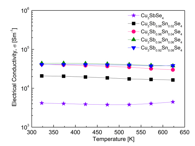
Figure 5 shows the electrical conductivity of Cu3Sb1-ySnySe4. With increasing temperature, the electrical conductivity of Cu3SbSe4 increased slightly, exhibiting non-degenerate semiconductor behavior. At a constant temperature, the electrical conductivity of the Sn-doped samples increased with increased doping levels. However, as temperature increased, the electrical conductivity of the Sn-doped samples decreased slightly, exhibiting degenerate semiconductor behavior.
Specifically, in our study, the electrical conductivity of Cu3SbSe4 was (4.2–4.5) × 103 Sm-1 at 323–623 K. The Sn-doped specimens exhibited significantly increased values of (2.1–4.1) × 104 Sm-1 at 323 K and (1.6–3.8) × 104 Sm-1 at 623 K. Yang et al. [5] reported a similar electrical conductivity for Cu3SbSe4, which was (4.9–5.2) × 103 Sm-1 at 323–623 K, as well as an increase in the electrical conductivity of Cu3Sb1-ySnySe4 (0.025 ≤ y ≤ 0.05) to (3.4–3.9) × 104 Sm-1 at 323 K and (2.4–2.6) × 104 Sm-1 at 623 K. The increase in conductivity was correlated to an increase in carrier concentration, from 7.5 × 10¹⁸ to 7.8 × 1019 cm-3 by Sn doping. Similarly, Wu et al. [11] measured a low electrical conductivity for Cu3SbSe4 at (1.0–5.0) × 103 Sm-1 at 300–570 K, while reporting an increase in the electrical conductivity of Cu3Sb0.98Sn0.02Se4 to (4.4–2.5) × 104 Sm-1 at the same temperatures. As shown in Figure 4, increased carrier concentration from Sn doping results in an increase in electrical conductivity. This increase in carrier concentration results from the excess carriers (holes) that are generated when Sn4+ is substituted for Sn5+.
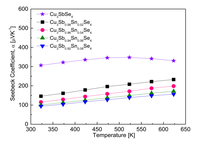
Figure 6 shows the Seebeck coefficient of the Cu3Sb1-ySnySe4 samples. All the samples behaved as p-type semiconductors, suggesting that the major carriers are holes, as confirmed by the positive Hall coefficients of the samples. The Seebeck coefficient for Cu3SbSe4 increased from 307 μVK-1 at 323 K to 348 μVK-1 at 523 K, and then decreased to 331 μVK-1 at 623 K. This suggests that the Seebeck coefficient for undoped Cu3SbSe4 decreases due to a rapidly increasing carrier concentration, caused by an intrinsic transition of undoped Cu3SbSe4 at temperatures above 523 K.
In contrast, the Seebeck coefficient for the Sn-doped specimens maintained a positive temperature dependence until 623 K, which suggests that intrinsic conduction may occur in Sn-doped specimens at temperatures above 623 K. As the Sn content increases, the Seebeck coefficient decreases because of the increased carrier concentration at constant temperature: 146–233 μVK-1 at 323–623 K for Cu3Sb0.98Sn0.02Se4, and 94–156 μVK-1 at 323–623 K for Cu3Sb0.92Sn0.08Se4. Yang et al. [5] reported a positive temperature dependence for Cu3SbSe4, with a Seebeck coefficient of 176–310 μVK-1 at 323–623 K. However, for Cu3Sb1-ySnySe4 (y = 0.025–0.05), the Seebeck coefficient decreased to 140–55 μVK-1 at 323 K and to 225–130 μVK-1 at 623 K. The decrease resulted from an increased carrier concentration from 7.5 × 10¹⁸ to 7.8 × 1019 cm-3. Similarly, Wu et al. [11] reported a high Seebeck coefficient of 220–390 μVK-1 at 300–570 K for Cu3SbSe4, but the coefficient decreased to 175 μVK-1 at 300 K and 190 μVK-1 at 570 K for Cu3Sb0.98Sn0.02Se4. Furthermore, Wei et al. [15] found that for Cu3Sb1-ySnySe4 (y = 0.01–0.04), the increase in carrier concentration to 1.8 × 1020 cm-3 caused by Sn doping decreased the Seebeck coefficient from 160 to 90 μVK-1 at 323 K and from 250 to 160 μVK-1 at 623 K.
Figure 7 presents the power factor (PF = α2σ) for Cu3Sb1-ySnySe4. The PF influences the power output in thermoelectric power generation. The Seebeck coefficient and electrical conductivity are each affected differently by carrier concentration [21]. In this study, the PF increased with increasing temperature. The PF of Cu3SbSe4 was relatively low, at 0.39–0.49 mWm-1K-2 at 323–623 K, with a low temperature dependence. However, as the Sn content increased, the PF and its temperature dependence rapidly increased, and thus the highest PF exhibited 0.55–1.18 mWm-1K-2 at 323–623 K for Cu3Sb0.96Sn0.04S4. Similarly, Yang et al. [5] reported that the PF of Cu3SbSe4 was 0.15–0.50 mWm-1K-2 at 300–673 K, and the PF was increased by Sn doping to 0.67–1.26 mWm-1K-2 at 300–673 K for Cu3Sb0.975Sn0.025Se4 (the authors did not provide the PF in the literature, but it was calculated from the Seebeck coefficient and electrical conductivity). Wu et al. [11] reported that the PF of Cu3SbSe4 was low at 0.1–0.4 mWm-1K-2 at 300–570 K, but that Cu3Sb0.98Sn0.02Se4 exhibited a higher PF of 0.8–1.3 mWm-1K-2 at 300–570 K.
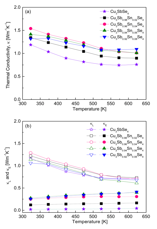
Figure 8 presents the thermal conductivity of Cu3Sb1-ySnySe4. As shown in Figure 8 (a), thermal conductivity tended to decrease with increasing temperature within our measured temperature range. Cu3SbSe4 had a thermal conductivity of 1.19–0.74 Wm-1K-1 at 323–623 K, whereas Sn-doped samples exhibited higher conductivity values of 1.34–1.54 Wm-1K-1 at 323 K and 0.90–1.09 Wm-1K-1 at 623 K.
Thermal conductivity (κ) is calculated as follows: κ = Dcpd, where (D) is thermal diffusivity, (cp) is specific heat, and (d) is density. Therefore, thermal conductivity can be influenced by phase, composition, and microstructure (grain boundary, defect, and pore, among others) in accordance with various preparation processes. For example, Yang et al. [5] reported thermal conductivity of 2.3–1.0 Wm-1K-1 at 323–623 K for Cu3SnySb1-ySe4 (y = 0.025–0.05) prepared by a melting-annealing process. Wu et al. [11] calculated a thermal conductivity of 1.25–0.91 Wm-1K-1 at 300–570 K for Cu3Sb1-ySnySe4 (y = 0–0.02) synthesized by wet chemical reaction with organic precursors and HP method. Wei et al. [15] calculated a thermal conductivity of 3.60–1.30 Wm-1K-1 at 300–673 K for Cu3SnySb1-ySe4 (y = 0.01–0.04) synthesized by MA and spark plasma sintering.
Compared with the above studies, the thermal conductivity in our samples, which were prepared by MA-HP, showed relatively low thermal conductivity values of 1.54–0.90 Wm-1K-1 at 323–623 K for Cu3Sb1-ySnySe4 (y = 0.02–0.08).
Thermal conductivity consists of lattice thermal conductivity (κL) and electronic thermal conductivity (κE), which are determined by the contributions of phonons and carriers, respectively [22]. These two contributions can be separated by the Wiedemann–Franz law (κE = LσT) as shown in Fig 8 (b), where T is the absolute temperature and L is the temperature-dependent Lorenz number [5]. The lattice and electronic thermal conductivity exhibited negative and positive temperature dependence, respectively. For Cu3SbSe4, the lattice and electrical thermal conductivities were 1.17–0.72 and 0.02–0.04 Wm-1K-1 at 323–623 K, respectively. In contrast, the lattice thermal conductivity of the Sn-doped specimens decreased from 1.06–1.29 Wm-1K-1 at 323 K to 0.61–0.73 Wm-1K-1 at 623 K because of the enhanced phonon scattering caused by ionized impurities. However, the electronic thermal conductivity of the Sn-doped samples increased from 0.12–0.27 Wm-1K-1 at 323 K to 0.16–0.41 Wm-1K-1 at 623 K because of the increased carrier concentration generated by the doping. With the increase in Sn doping, the lattice thermal conductivity did not change significantly, whereas the electronic thermal conductivity increased. Therefore, although the total thermal conductivity of Cu3Sb1-ySnySe4 appears to be attributed mainly to its lattice thermal conductivity, the change in total thermal conductivity can be attributed mainly to its electronic thermal conductivity.
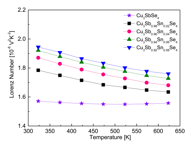
Figure 9 shows the temperature dependence of the Lorenz number for Cu3Sb1-ySnySe4. The Lorenz number ranges (1.45-2.44) × 10-8V2K-2, with lower values indicating non-degenerate semiconducting behavior and higher values indicating degenerate semiconducting or metallic behavior [23]. The Lorenz number was estimated with the equation L[10–8V2K–2] = 1.5+ exp[–|α|⁄116] [24]. The Lorenz number for Cu3SbSe4 was (1.57–1.56) × 10-8 V2K-2 at 323–623 K, indicating non-degenerate semiconducting behavior. However, as the Sn content increased, the Lorenz number increased at constant temperature to (1.78–1.94) × 10-8 V2K-2 at 323 K and to (1.63–1.76) × 10-8V2K-2 at 623 K. In comparison, Prasad et al. [14] reported the Lorenz number for Cu3Sb1-ySnySe4 (y = 0–0.04) was (1.57–1.89) × 10-8 V2K-2 at 323 K.
Figure 10 presents the ZT for Cu3Sb1-ySnySe4, where ZT = α2σκ-1T. As can be observed, ZT increases with increasing temperature, which is a result of the temperature dependences of the PF (Figure 7) and thermal conductivity (Figure 8). The ZT of Cu3Sb0.96Sn0.04Se4 was increased significantly by Sn doping (highest ZT of 0.71 at 623 K), compared with a ZT of 0.39 at 623 K for undoped Cu3SbSe4. This great increase was due to the remarkably improved PF, despite the increased thermal conductivity caused by Sn doping.
Yang et al. [5] reported a ZT of 0.04 for Cu3SbSe4 and a ZT of 0.75 Cu3Sb0.975Sn0.025Se4 at 673 K prepared by encapsulated melting and annealing method. Wu et al. [11] achieved a ZT of 0.24 for Cu3SbSe4 and a ZT of 0.48 for Cu3Sb0.98Sn0.02Se4 at 570 K synthesized by wet chemical reaction and HP processes. Wei et al. [15] reported a ZT of 0.30 for Cu3SbSe4 and ZT of 0.69 for Cu3Sb0.98Sn0.02Se4 at 673 K, prepared by MA and spark plasma sintering. In this study, the MA-HP method used for solid-state synthesis was validated as an economical and practical process to save time and energy in preparing Sn-doped permingeatite compounds.
4. CONCLUSIONS
Herein, permingeatites Cu3Sb1-ySnySe4 (y = 0–0.08) were successfully prepared by employing an MA-HP process, and the thermoelectric properties of the permingeatites were examined at various levels of Sn doping. All the samples contained a single permingeatite phase of tetragonal structure without secondary phases. Undoped and Sn-doped samples exhibited p-type semiconductor behavior. Cu3SbSe4 exhibited non-degenerate semiconductor behavior, whereas Sn-doped samples transitioned to degenerate semiconductor behavior. As the Sn content increased, the PF was enhanced because of decreased Seebeck coefficient and increased electrical conductivity. However, thermal conductivity also increased with increasing electronic thermal conductivity, because of increased carrier concentration. Therefore, Cu3Sb0.96Sn0.04Se4 exhibited the highest ZT of 0.71 at 623 K because it had the highest PF (1.18 mWm-1K-2).


