


1. Introduction
Pure titanium (cp-Ti) and its alloys are widely employed as dental implant materials in the dentistry fields because of their excellent corrosion resistance, biocompatibility and mechanical properties. The use of these titanium materials is also important to inducing stable osseointegration in vivo to reduce failure [1,2]. However, the naturally occurring oxides on titanium metal surfaces do not form a direct chemical bone/material interface. For this reason, studies have been conducted to modify surface roughness, to improve the binding force between the implant and bone. Studies have investigated many ways to improve implant surface modification for biomedical procedures, using implant surface coating techniques such as ion implantation, magnetron sputtering, biomimetic coating, and cathodic electrodeposition [3-9]. Among these methods, surface treatment by high voltage anodization, such as plasma electrolytic oxidation (PEO), produces a titanium oxide film on the implant surface [10-12].
PEO can be used to create a stable oxide film from various solutions, to provide corrosion protection and bio-functional properties on the metal surface. The pore shape and size formed in the oxide film by PEO can be controlled by the applied potential and current density, electrolyte composition and concentration, solution temperature and pH, etc. [13,14]. Recently, a PEO process to improve biocompatibility was performed using electrolytes containing Ca and P ions [15].
Natural bones consist of various minerals including magnesium, silicon, zinc, strontium, and manganese. Among these elements, Mg is the most important ion, related to bone bioapatite. Sufficient Mg and Ca provide powerful and healthy bone, and they reduce the risk of osteoporosis. About 60 to 65% of the total amount of Mg in the human body is ound in bones and teeth, and 35 to 40% of the total Mg is distributed in muscle tissue, nerves and other soft tissues and fluids [16-19]. Si is also an important factor in the growth and development of bone and connective tissue. It is present in osteoblasts with metabolic activity and is believed to be essential for forming extracellular matrix in bone and cartilage [20-24].
In the PEO process, doping the surface with functional elements will increase the hardness of the surface and increase the adhesion strength of the coating on the surface. Conventional implant surface treatments have disadvantages, in that hydroxyapatite (HA) coated films, which are prepared using a physical method on the surface, can separate from the implant substrate after clinical implantation. On the other hand, because the PEO-treated surface is doped in the PEO process, it is a method to delete the defect that is clinically separated at the boundary between the implant surface and coated layer due to the decrease of the adhesion force.
The detachment of the coating layer is closely related to the dissolution of ions on the surface as a result of clinical use in body fluids. In electrolytes containing Mg and Si ions, it is important to improve the titanium oxide layer, which exhibits the bioactive surface by PEO treatment. However, the adhesion and corrosion behaviors of Si and Mg-doped TiO2 films, or HA films, have rarely been studied. Si and Mg ions can affect the composition and morphology of the films, and the biological response of TiO2 is currently unclear.
Few studies so far have investigated the actual implant surface. Most studies have observed the morphology of the coating on the PEO-treated surface, and few studies have measured the bonding strength when only Mg and Si were coated. To improve the corrosion resistance and adhesion force of dental implants, we investigated silicon and magnesium coatings on the Ti alloy surface doped with Ca and P for biocompatibility.
2. Experimental Procedure
Disk type Ti-6Al-4V alloy (Timet Co., USA) was prepared as the substrate material (t: 3 mm, φ: 10 mm) for coatings under investigation. Samples were polished with #100 ~ # 2000 grit sandpaper. A dental implant fixture was made using the Ti-6Al-4V alloy, and grade 5 (Timet Co., USA) was used as the substrate for coatings. Samples for PEO treatment were prepared by machining with a milling instrument. The implants and disk prepared without PEO treatment were thoroughly washed with distilled water and sonicated in ethyl alcohol for 10 minutes before use as a control.
The sample and Pt were set up as the anode and cathode in the electrolyte medium, respectively. A pulsed DC power supply was used. The formation of micro-pores on the titanium alloy surface was carried out by electrochemical methods. Solutions of calcium acetate monohydrate and calcium glycerophosphate containing Si and Mg ions were prepared for the electrolyte. PEO was performed at constant voltage (280V) for 3 minutes (KDP-1500, Korea). The temperature of the electrolyte was maintained below 25 °C by cooling system. The Si and Mg ion-doped HA film formed on the Ti-6Al-4V surface was characterized by X-ray diffractometer (XRD, X'pert, Philips, Netherlands). The surface of the Si and Mg ion-doped HA film on the Ti-6Al-4V sample was investigated by field emission scanning electron microscope (FESEM, S-4800 Hitachi, Japan). Energy dispersive X-ray spectroscopy (EDS, Inca program, Oxford, UK) was employed to analyze the Si, Mg, Ca, and P spectra after PEO treatment.
The adhesion strength of the PEO-treated surface was investigated using a scratch tester (US 12/324, Anton Paar, Austria). The total test length of 5 mm was scratched with a starting load of 50 mN and ending load of 10,000 mN with a loading speed of 10 mm/min.
An anodic potentiodynamic polarization test was performed in 0.9% NaCl solution at 36.5±1 o C using a potentiostat (EG&G Co., PARSTAT 2273, USA) with a three-electrode system. The preparation of the sample was the same as described for the samples for PEO treatment above. The NaCl solution was deaerated by Ar gas for 30 min during the corrosion test. The potentiodynamic polarization test was carried out at -1500 mV ~ +2000 mV of applied potential with a scan rate of 1.67 mV/s. A Tafel extrapolation was carried out to determine the corrosion parameters using a software-based approximation.
3. Results and discussion
Table 1 shows the micro-pore size and area ratio obtained for the Si and Mg ion-doped HA films, including the number of pores/(10 µm)2, larger size of pores per unit area (10 µm)2, and minimum size of pores occupying the unit area (10 µm)2. From the image analysis, the pore numbers increased in the order of 28.6 (CaP), 33.5 (5Mg/5Si), 34.5 (10Mg/5Si), and 37.1 (20Mg/5Si). And the maximum micropore size occupied by unit area on the CaP, 5Mg/5Si, 10Mg/5Si, and 20Mg/5Si samples were 25.15, 24.25, 19.35, and 17.25, respectively. Also, the minimum micro-pore size of occupied by unit area on the CaP, 5Mg/5Si, 10Mg/5Si, and 20Mg/5Si samples were 2.0, 2.5, 2.5, and 2.8, respectively, as shown in Table 1.
In the PEO process, the pore formation process was affected by various conditions, and the mechanism is explained as follows [25]. The PEO steps were to form and grow a passivation film on the substrate by applying an extremely high voltage to the electrolyte. As the thickness of the oxide layer increased, the voltage between the substrate and the electrolyte increased. The weak part of the oxide layer will suffer dielectric breakdown due to the high voltage. The oxide layer melted by the high temperature generated in the micro-discharge region tends to be ejected from the substrate coating interface to the coating surface, leading to rapid solidification and recrystallization by the cooling electrolyte. In the end, it is possible to obtain coatings composed of complex compounds in various electrolytes.
In the case of a PEO-treated surface in a solution containing Si and Mg ions, MgO and Mg2SiO4 can be formed in the oxide film by sparking the anodic oxidation. MgO is formed by dissolving the oxidized O2- from the electrolyte, by ejecting Mg2- out of the substrate and by reaction. And the presence of Mg2SiO4 showed the presence of the anionic SiO32-. At high temperatures, SiO2 and MgO are present in a fused state, but during the spike of anodic oxidation and spacing of micro-arcs, due to the cooling effect of the electrolyte, the fused SiO2 and MgO will form Mg2SiO4, as shown in the following reactions;
Therefore, the microstructure of the generated PEO layer depends on the type of micro-discharge in the PEO process, and the composition of the electrolyte, such as Mg and Si, affects the morphology of the PEO and the change in the size of the pores [15,18].
Fig 1 shows FESEM images of Si and Mg ion doped HA films formed on Ti-6Al-4V alloy at 280V in various electrolytes, to confirm the data obtained above, as shown in Table 1. In Fig 1, Fig 1(a) is CaP, (b) is 5Mg/5Si, (c) is 10Mg/5Si, and (d) is 20Mg/5Si Si, respectively. From Fig 1, the Si and Mg ion doped HA films showed small and large micro-pores with uniform distribution after PEO treatment. This confirmed that Mg ions act to control the formation of the HA films and micro-pore size on the Ti-6Al-4V alloys in the process of PEO. In particular, the micropores formed on the 5~20Mg/5Si coated samples were smaller than those of the Si and Mg ion-free HA coated surfaces, as the Mg ion concentration increased, as shown in Fig.1
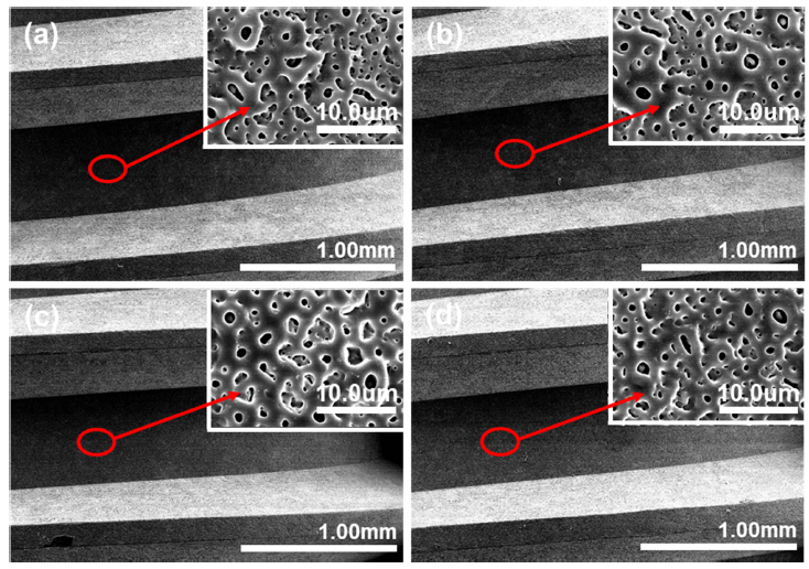
Fig 2 shows FESEM micrographs of the Si and Mg ion-doped HA films formed on the dental implant by PEO treatment. Fig 2 shows the implant surface at low magnification and high magnification: Fig 2(a) is CaP, (b) is 5Mg/5Si, (c) is 10Mg/5Si, and (d) is 20Mg/5Si, respectively. From Fig 2, the surfaces of the PEO-treated implants are composed of micro-pores like the pores formed on the plate-type specimens shown in Fig 1. For implants, the pores formed on the top, valley, and crest of the screw should be uniform, and it was confirmed that the pores were uniformly formed from Fig 2.
This uniform porous surface is important to shorten the healing time after implantation, and provides a surface that promotes cell growth and differentiation. These micro-pore surfaces on the dental implant provide a good environment between the bones and implant interface, for bone connectivity [11]. In particular, with pores formed on the surface of dental implants, because the heat of friction between the bone and the surface results in necrosis of the bone during clinical implantation, research on wear characteristics will be carried out in future research. That is, the surface roughness is important in dental implants, and since Ra is usually maintained at about 1.6 μm, appropriate roughness can be imparted by sandblasting after milling.
The surface roughness of the porous surface formed using the PEO method was less than 1.0 µm, so it does not affect the generation of bones and heat of friction.
In this study, it was necessary to investigate the dissolution of ions on the pore - formed surface before investigating the friction characteristics.
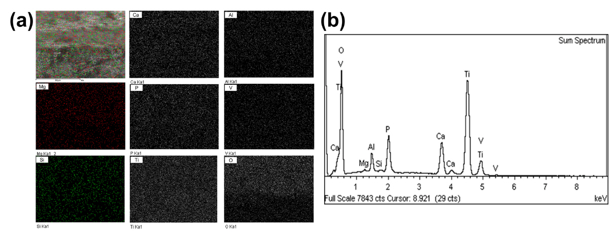
Fig 3 presents the EDS analysis data for the 5Mg/5Si samples after PEO treatment of the dental implant. Fig 3(a) is an FE-SEM image and dot mapping, Fig 3(b) shows the EDS peaks of elements on the specimen surface. The peaks of Si, Mg, Ca, and P were observed and were well distributed on the PEO-treated surface, especially, on the top, valley, and crest of the screw. From the results of EDS mapping, Si, Mg, Ca, and P had a uniform distribution on the surface of the dental implant. This confirms that these functional elements can be homogenized over the entire surface of the dental implant by PEO treatment. Generally, with dental implants, it is difficult to coat HA using a physical vapor deposition method because the surface morphology is formed on the screws, but the PEO method provides a uniform coating on the surface.
Fig 4 shows the EDS analyses performed to verify the compositions of the Si and Mg ion-doped HA films on the Ti-6Al-4V alloy surface. Fig 4 presents the contents of elements in the Si and Mg ion-doped HA films after PEO treatment in electrolytes containing Si, Mg, Ca, and P ions. Fig 4(a) is Ca, (b) is P, (c) is Mg, and (d) is Si, respectively. From Fig 4, the contents of Ca element for CaP and 5~20Mg/5Si were 7.50, 7.20, 6.66, and 6.15, and contents of P element for CaP and 5~20Mg/5Si were 5.35, 5.01, 5.05, and 5.16. Also, the contents of Mg and Si element were 0.23, 0.28, and 0.30 and 0.21, 0.29, and 1.02, respectively. This shows that the ratio of Ca and P on the Si and Mg ion-free HA coated Ti-6Al-4V alloy surfaces was 1.40, whereas, the Ca/P ratio on the xMg/5Si samples formed on the Ti-6Al-4V alloy without Si and Mg was 1.44, 1.32, and 1.19. The (Ca+Mg/P+Si) ratio including Si and Mg was 1.41 at 5Mg/5Si, 1.33 at 10Mg/5Si and 1.3 at 20Mg/5Si. These results suggest that Ca decreased and Mg increased at the same time, which means that Ca is replaced with Mg, competitively. The Ca/P ratio decreases with the addition of Mg content in the electrolyte, which is considered to be influenced by Mg ions which inhibits HA growth [18,31].
Fig 5 presents the TF-XRD patterns of the Si and Mg ion HA film formed on the Ti-6Al-4V alloys anodized at 280 V for 3 min: Fig 5(a) is CaP, (b) is 5Mg/5Si, (c) is 10Mg/5Si, and (d) is 20Mg/5Si, respectively. Diffraction peaks of TiO2 were observed for the Si and Mg ion HA film formed on the Ti-6Al-4V alloy. Fig 5 shows anatase TiO2 from the # 21-1272 ICDD file and rutile TiO2 from the # 21-1276 ICDD file. These phases were formed on the exposed surface during the PEO process at high temperature. The anatase TiO2 phase provides a good structure for cell proliferation on the dental implant [11].
In particular, the peak of HA shifted to the left as the Mg ion concentration increased. These results suggest that Mg and Si ions affect the surface reaction between Ca and P ions. That is, the decrease in HA crystal lattice due to the substitution of two ions by the PEO process seems to affect the pore shape because of the difference in the ionic radius of Ca2+ (0.099 nm) and Mg2+ (0.069). Also, the increase in Mg concentration seems to be due to the relative loss of Ca2+ which resulted in the increase in the amount of Mg2+ replaced with Ca2+, thereby reducing the crystallizability of the Mg-HA formed on the alloy surface [15,18]. Therefore, it can be assumed that the HA peaks shifted from pure HA peaks due to lattice distortion by ion substitution [32].
Figs 6 and 7 show the scratch test results of the PEO-treated samples. Fig 6 (a), (b), and (c) are 5Si, 10Si, and 20Si. Fig 7(a), (b), and (c) are 5Si, 10Si, and 20Si. The adhesion force of the Si-doped HA film was measured by scratch test, and it appeared that the adhesion forces of 5Si, 10Si, and 20Si-doped HA films were 0.5N, 0.5N, and 1.3N. In the case of Mg, the adhesion forces of the 5Mg, 10Mg, and 20Mg-doped HA films were 0.7N, 2.2, and 2.0N, respectively. From the results, the adhesion forces of Si and Mg doped HA films increased with Mg and Si ion concentrations, as shown in Table 2.
It is thought that Mg and Si act to increase hardness and the bonding force between the HA film and Ti substrate, due to mechanism of solid solution and increasing the densified inner layer by PEO treatment [25].
The inorganic material layer manufactured using the PEO technology is expected to provide excellent hardness and adhesion similar to ceramics with a relatively thick and dense structure. A previous researcher reported that the hardness values o f inorganic layers formed on Mg alloys in aluminate-silicate electrolytes were higher than those obtained in phosphate-based electrolytes. This is believed to be because the hardness value of spinel Mg2SiO4, which is the main phase generated in the former electrolyte, is higher than that of MgO and Mg3(PO4)2, which are the main phases generated in the counter electrolyte [33]. The hardness and adhesion force values c an vary depending on the substrate condition, electrolyte composition, current density, and processing time, which determines the major phase components [34]. Therefore, when PEO treatment is performed in an electrolytic solution containing Si and Mg, the formation of Mg2SiO4 is increased, hardness is increased, and as a result, it is considered that the adhesion strength is increased.
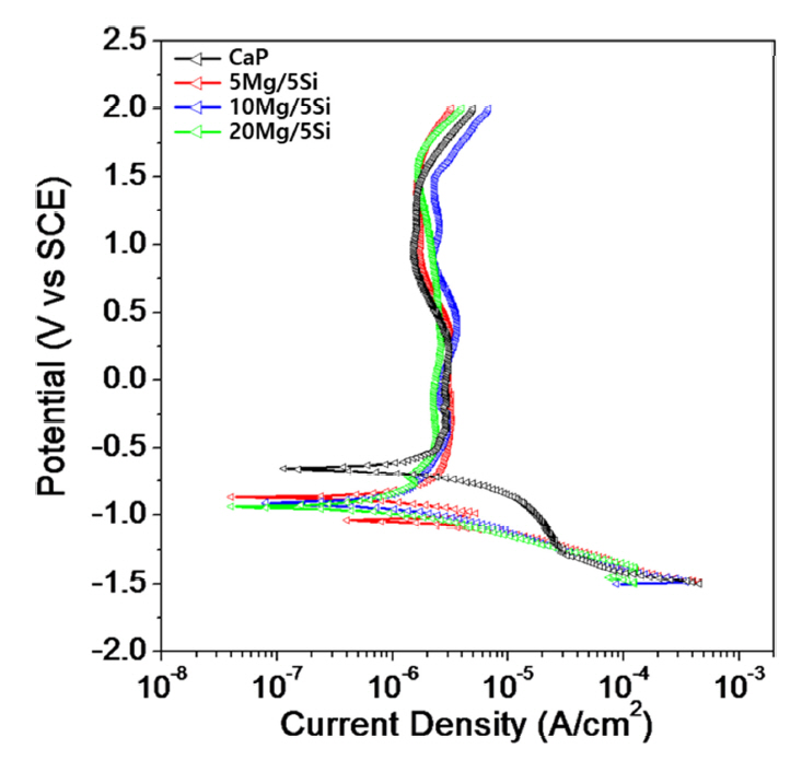
Fig 8 shows the potentiodynamic polarization curves obtained for the Si and Mg ion-doped HA films on the Ti-6Al-4V alloy in 0.9 wt% NaCl electrolyte at 36.5±1 o C. The corrosion parameters obtained from anodic polarization are summarized in Table 3. Table 3 shows the corrosion behavior with corrosion potential (Ecorr), corrosion current density (Icorr), primary passivation current density (Ipp), and current density at 300mV (I300) for Si and Mg ion-doped HA films on the Ti-6Al-4V alloy. Even though the corrosion potential (Ecorr) of the 5~20Mg/5Si HA film formed Ti-6Al-4V alloy decreased, a passive region remained longer than in the CaP film formed Ti-6Al-4V alloy. The corrosion potential (Ecorr) was - 640 mV for the CaP, - 860 mV for the 5Mg/5Si, - 910 mV for the 10Mg/5Si, and - 940 mV for the 20Mg/5Si, respectively. The corrosion current density (Icorr) was 2.73×10⁻⁶ A·cm2 for the CaP, 2.29×10⁻⁶ A·cm2 for the 5Mg/5Si, 2.42×10⁻⁶ A·cm2 for the 10Mg/5Si, and 2.20×10⁻⁶ A·cm2 for the 20Mg/5Si, respectively.
Corrosion potential and density mean the potential for first time oxidation. This is related to the electromotive force (EMF) in metals. On a pore formed surface, generally, corrosion potential is lower than a bulk surface due to playing role in corrosion site at pore as anodic electrode. From the anodic polarization curves results, in general, the pore-formed surfaces showed higher corrosion current density and lower corrosion potential compared to the bulk specimen. Specifically, corrosion potential decreased as Mg content increased. This is consistent with Mg having the lower EMF, and being easily released on the surface. Therefore, corrosion potential was decreased by adding more Mg ions to the electrolyte.
Also, Ipp was 2.94×10⁻⁶ A/cm2 for the CaP, 3.18×10⁻⁶ A/cm2 for the 5Mg/5Si, 2.84×10⁻⁶ A/cm2 for the 10Mg/5Si, and 2.38×10⁻⁶ A/cm2 for the 20Mg/5Si, respectively. The current density at 300 mV (I300) was 3.01×10⁻⁶ A/cm2 for the CaP, 3.22×10⁻⁶ A/cm2 for the 5Mg/5Si, 3.51×10⁻⁶ A/cm2 for the 10Mg/5Si, and 2.64×10⁻⁶ A/cm2 for the 20Mg/5Si, respectively. In all specimens, a passive region due to passive film formation was observed.
The HA film surface with Si and Mg ions showed lower Ecorr and Icorr compared to the HA film surface without Si and Mg ions. And the Ipp and I300 for 5~20Mg/5Si formed on the Ti-6Al-4V alloy were lower than that of the surface coated with HA without Si and Mg ions. It was confirmed that, in the region of passivation, the PEO-treated surface exhibited a lower current density and longer passive region, due to the formation of a stable and thick passive film. In addition, according to a report, when PEO treatment is performed on an Mg alloy in an electrolyte containing Si, a coating layer composed of MgO and Mg2SiO4 is formed on the surface. When this surface was subjected to a corrosion test in a 3.5 wt% NaCl solution, the Icorr value decreased by three orders of magnitude, and it was reported that the corrosion resistance greatly increased [35,36]. In this study, the Icorr and I300 values a lso tended to decrease as the concentration of Mg ions increased.
The results indicate that an oxide film formed during the PEO process can protect against aggressive ions in the corrosion environment. As a result, the rate of dissolution can be controlled by the doped elements, which contain functional elements, coated on the surface of the HA using the PEO method.
4. Conclusions
The Si and Mg ion-doped HA films exhibited small and large micro-pores with uniform distributions after the PEO treatment. The micro-pores formed on the 5~20Mg/5Si coated samples were smaller than those of the Si and Mg ion-free CaP coated surfaces, as the Mg ion concentration increased. The peaks of Si, Mg, Ca, and P were observed and were well distributed on the PEO-treated surface, especially on the top, valley and crest of the screw. The Ca/P ratio decreased with the increasing Mg content in the electrolyte. The diffraction peak of anatase TiO2 was observed in the Si and Mg ion HA film formed on the Ti-6Al-4V alloy. The adhesion force of the Si and Mg doped HA films increased as Mg and Si ion concentrations increased. A passive region due to passive film formation was observed, the HA film surface with Si and Mg ions showed lower Ecorr and higher Icorr compared to the HA film surface without Si and Mg ions. And the Ipp and I300 for 5~20Mg/5Si formed on the Ti-6Al-4V alloy were lower than that of the surface coated with HA without Si and Mg ions.